TLDR:
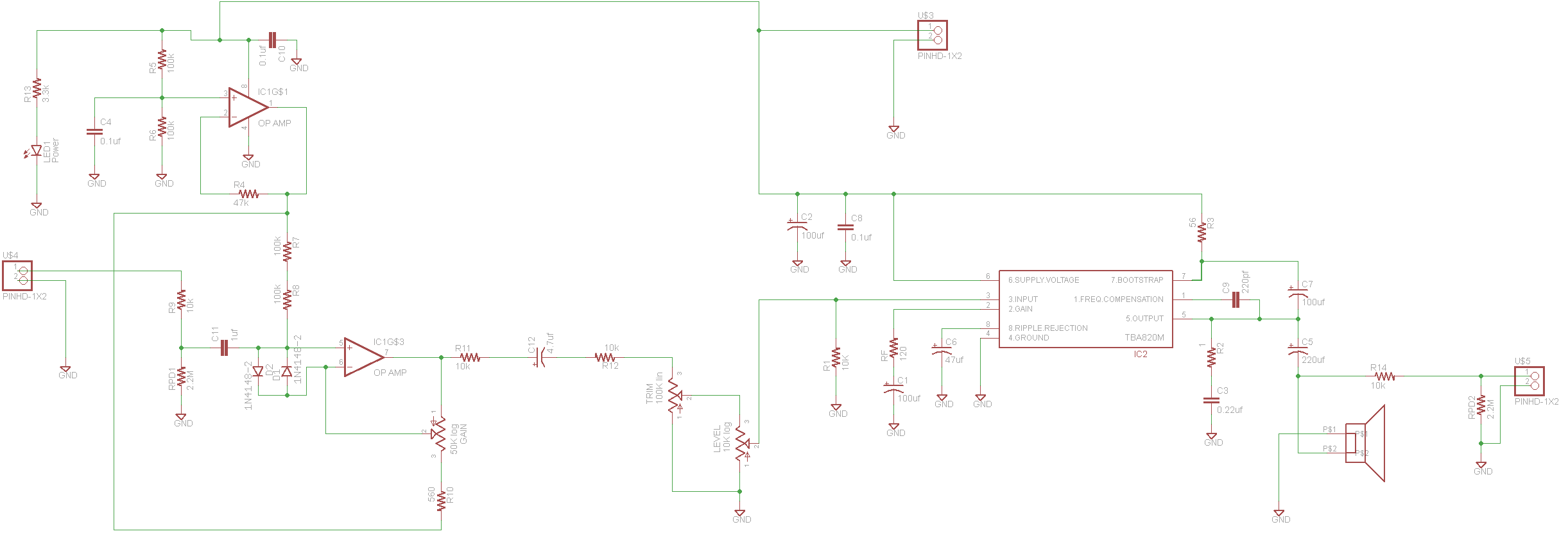
If you are just looking for the Stella Amp schematic, then follow that link, or head over to the downloads page where you can download the schematic and the original Eagle design files.
Design
On this page I'm going to walk you through my design process for the Stella Amp. (One point of order before I begin: I know that many of the images below are "too big" and overlap the right margin of the page. I'm really okay with this, and I did it intentionally. Clarity of the figures is more important for me than consistency in margin width.)
The setup
I built a few LM386 based guitar amps, and I checked out quite a few LM386 based amps on youtube, and to me they all had a similar sound. Although there are some sonic differences amongst the various flavors of LM386 amps, they're really more alike than not alike.
I suspect that the more alike than not part is because it's all the same chip, even if you radically change the supporting circuitry. Plus many of those amps use little teeny speakers.
I wanted something different. Something versatile. And something with a good clean tone!
Back-end:
I started by looking for chip amps which were a little more powerful than an LM386. But not too powerful; I wanted to keep the amp battery powered, small enough to fit in a variety of enclosures, and I wanted to avoid heat sinks.
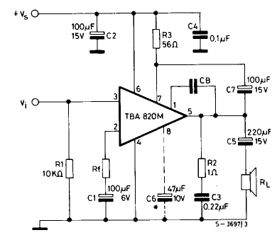
The TBA820M was one of the first chips I found. 8 pins, through hole, 1 - 2 watts depending on supply voltage and output load. Perfect. I checked out the data sheet and was encouraged by the example schematic. With all of those external components, I would almost certainly get a different sound, one way or another.
I was disappointed that there wasn't more info in the datasheet about all of the pins and what they do, and I wanted to see more example circuits. I was happy to see the complete schematic for the chip included in the datasheet, and it looked pretty simple. Simple is good.
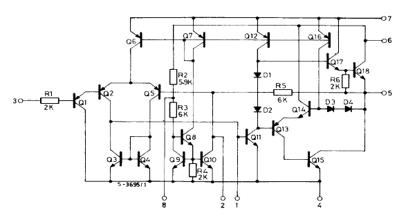
I'm trying to learn enough analog circuit design to understand this. So far I recognize a current mirror and a differential input stage, but I couldn't tell you how it all hangs together.
Many chip amps have built in overvoltage, short circuit, and thermal overload protection circuitry. That's fine if you want to run them in the linear range. But if you want to drive the amp into distortion, then those protection circuits can often thwart you. You'll get distortion all right but it will be coming from the protection bits not the amp.
(Now, a caveat. Don't let me deter you from trying out some other chip that sounds interesting but has protection circuitry built in! Wire it up and give it a shot!)
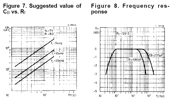
Anyway. I did see a couple aspects of the TBA820M example circuit that were open to hacking. One was the frequency compensation capacitor CB. With a CB value of 220pf, the frequency response of the output stage is 25-20,000 Hz. At 680pf the frequency response is 25-7,000 Hz.
The other was resistor Rf. Adjusting Rf adjusts the gain. The example schematic has Rf at 120 ohms, but the datasheet claims that 33 ohms will give higher gain but with more distortion. Also there is a relationship between Rf and CB, as per the datasheet:
What's it going to sound like? Who knows? Let's find out!
I ordered the parts and breadboarded it up. I built it with a 680pf capacitor because I forgot to order a 220 pf capacitor. I tested it with an old CD player I had laying around and it sounded... muffled. In a fit of impatience I built a 220 pf equivalent capacitor out of several other capacitors I had laying around. I fired up the CD player and it sounded great!
I decided not to mess with adjusting Rf and CB and to stick with the default example circuit. I soldered it into some RadioShack protoboard I had laying around and turned my attention to the front end.
Front end:
One of my original design goals for the Stella amp was for it to have an effective built in pre-amp. I wanted to allow cigar box guitars equipped with piezo pickups to be played directly into the amplifier with no preamp.
I tried the Tillman preamp and the MPF102 variation and what I found was that neither of them could amplify the signal enough to drive the amp stage into distortion. I concocted a few schemes with cascading jfet stages but quickly realized I didn't know what I was doing. Trial and error wasn't working and I didn't have the chops to design a cascaded jfet input stage which had the sonic and electrical characteristics that I was looking for.
I do know a bit about opamps however.
A short digression on powering op amps
Opamps are traditionally powered via a dual supply with two power rails, usually +15 and -15 or +12 and -12 volts. Picture the AC signal centered at zero volts. With a +15/-15 supply, the op amp has a lot of room to work with that signal without causing any distortion.
Another reason why opamps were powered with such a large voltage range is that older opamps couldn't push their outputs within a few volts of either supply rail. Some newer opamps, called "rail to rail" opamps, can swing their output from the positive supply rail to the negative supply rail.
Rail to rail op amps are great because we can get away with using less voltage for the same amount of headroom. The downside is they are a bit more expensive.
Generating dual supplies (especially ones involving negative voltage) from a battery is possible but inconvenient. Why not just shift the whole circuit up a few volts? The opamp doesn't care if it is powered by +4.5/-4.5 volts with the signal at 0 volts, or if it is powered by +9 and 0 volts, with the signal centered on 4.5 volts.
But if we give the opamp 9 volts on the positive supply rail, and 0 volts on the negative supply rail, we need our "ground voltage" for the whole opamp front end to be at 4.5 volts.
Having a ground voltage that is not actually at zero volts is called a virtual ground. Here is our virtual ground circuit (freely stolen from A Single-Supply Op-Amp Circuit Collection by Texas Instruments):
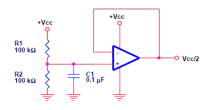
The 100k resistors form a voltage divider that doesn't take much current to maintain. The capacitor helps stabilize the divider under load or trash on the supply line. (We're powering this with a battery, so what trash could we see? Well, never underestimate Murphy's law. Plus, nothing is stopping anyone from building a power supply and running the amp off the mains.)
That voltage divider feeds into the opamp configured as a voltage follower. The opamp then buffers the output and keeps it at half the supply voltage.
Note the datasheet says the performance deteriorates at low frequencies. What are "low frequencies" in this context? They don't say. Could be audio frequencies, could be sub-audio frequencies. And what happens when performance deteriorates? I decided not to worry about it and just see how it performed in real life.
One adjustment I made was to put a 47k resistor in the negative feedback path of the opamp. This equalizes the resistance that each input sees looking out of the opamp. (Do the Thevenin equivalent circuit for the voltage divider and see!)
Here's the completed virtual ground circuit:
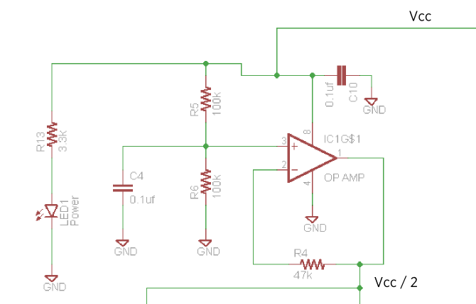
So when you look at this chunk of the schematic, just think "this is the bit that generates Vcc/2".
With all of that as background, let's get into the whys and wherefores of the front end.
Our front end is a non-inverting, 1-80x opamp gain stage.
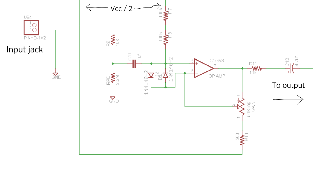
R9 is a 10k protection resistor. It will limit the current of any voltage spikes or overvoltage on the input.
Rpd1 is a pulldown resistor. If you like the distortion performance of the Stella amp, you can add a few extra components and turn it into a distortion pedal and use it with your main rig. If you turn the Stella into a pedal, Rpd1 will help limit pops when you stomp on your stompbox. If you only use the amp as an amp, you can ignore Rpd1 (you should probably still solder it in though, it won't hurt anything.)
C11 is a 1 uF coupling capacitor, and C12 is a 4.7 uF coupling capacitor. Remember a capacitor blocks DC voltage and lets AC voltage through. Our incoming guitar signal is centered on 0 volts and swings between about +0.5v and -0.5v. We need to push it up to half the supply voltage for the opamp. (That's what the Vcc/2 circuit is for.) But we don't want that 4.5 dc (otherwise known as the bias voltage) to leak back out into our guitar (or maybe a stompbox or preamp we've plugged in). Also we don't want it to leak into the amp stage, which requires a signal centered on zero volts.
R8 and R7 are 100k resistors that feed the 4.5 volts to the incoming signal, bringing up the level to the level we want. These two resistors essentially set the input impedance of the amp to 200k ohms. (Why two 100k resistors instead of one 220k resistor? It's one less part number to keep track of.)
So the input impedance of the first stage is 200k ohms, and the first coupling capacitor is 1uf. What is the R-C filter cutoff?
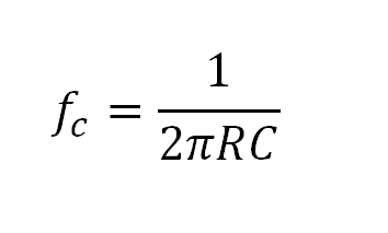
R is in ohms and C is in farads. If we work out the sum, it means we will pass everything above 0.8 Hz.
The second coupling capacitor is 4.7uf, and when I did the parallel resistance calculation on everything between the front end and the amp, I got a value of ~4.7k ohms. Do the math on that and the R-C filter cutoff is 7.1 Hz. (Plug: if you want to do the math on RC filter cutoffs easily, check out this awesome RC filter cutoff calculator @ AMZ FX. http://www.muzique.com/schem/filter.htm )
The TBA820M itself has a frequency response down to 25 Hz, and at 2 watts you're not going to be shaking much booty with your bass. But if you turn it into a distortion pedal...
Moving on: D1 and D2 are input protection diodes. In theory, the positive and negative inputs of the opamp should always be at the same voltage. Since we're feeding the output of the op-amp back to one of the inputs, the output of an ideal op-amp needs to swing the output just as fast as the input signal.
In theory. In practice, the opamp can only swing the voltage so fast in either direction (this is called the slew rate). If a static electric shock or other voltage spike comes down the line, the slew rate of the opamp isn't going to be fast enough to adjust the output voltage in time. This will cause current to flow *into* the base of the input transistors and damage them. D1 and D2 shunt this extra voltage potential before the input transistors have a chance to reverse bias themselves.
Yes, the opamp that comes with the kit has built in protection diodes on the chip itself. But if you don't like the opamp that comes with the kit you can substitute it for an opamp you like, which may or may not have protection diodes.
Now for the gain pot and R10. Take a look at the classic non-inverting amplifier circuit and compare it with the Stella circuit:
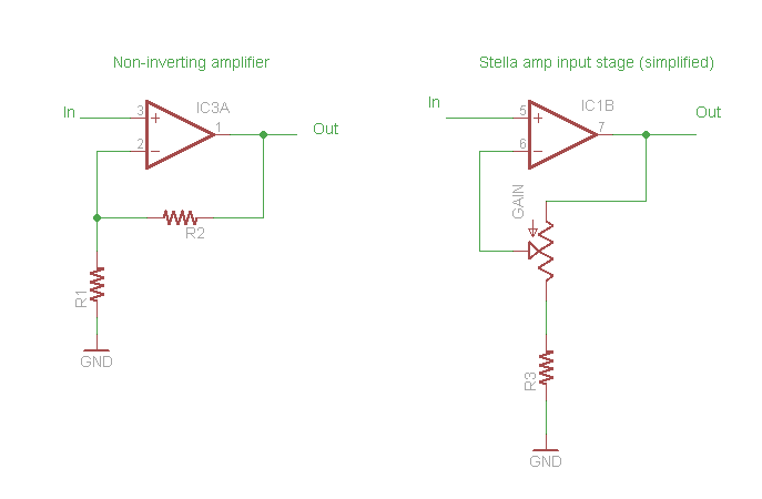
The gain of the non-inverting amplifier is 1 + (R2 / R1). What does that mean? If we set R1 at 10k and R2 at 1k our voltage gain would be 10. As we lower R1, we lower the gain. When R1 gets to zero, the gain is essentially 1, or, in other words, there is no gain at all. As we increase R1 we raise the gain.
Now look at the simplified Stella amp circuit. When the level pot is cranked all the way down, it's a voltage follower -- the output voltage of the opamp will exactly track the input. When the pot is cranked to the maximum, the gain is determined by R3 and the value of the pot. For the Stella amp, the value of the pot is 50k and R3 (well, the Stella amp part number is R10) is 560 ohms, making the maximum gain 90, more or less. (At higher supply voltages this may not be enough gain to drive the opamp into distortion. This may, or may not be what you want. Reducing R10 to 470 or even 330 will up the gain, although at 330 I find it a bit too unstable at higher gains for my taste.)
As far as which op-amp to use, I started out with a TS911. In testing I switched to an MC33202PG because I felt it had a smoother sound when distorting. You can use any op-amp you want, it doesn't have to be a rail to rail op amp! This is especially true if you are powering your Stella amp with 9 volts or greater.
Finally, R11. R11 limits how much current the opamp has to deliver, as well as helps bring the voltage down a little bit.
Front end and back end glue:
Check it:
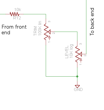
R12 (with R11) helps bring the voltage down a little bit from our rail to rail op amp.
Now, look at the TRIM pot and the LEVEL pot. What the heck is going on here? Let me explain how I arrived at that setup.
Imagine the trim pot was not there. If the trim pot was not there, the output would go right into the top of the level pot, and from the wiper of the level pot it would go into the gain stage. That's the configuration I started with.
Ah, but there is a problem. If I was optimizing for one supply voltage I could calculate or experimentally determine the best value for R12. But at different supply voltages it all breaks down. At one value of R12 at a certain supply voltage (I don't remember the details anymore, sorry) there was WAY too much distortion and it all sounded like crap. The part of the dial that sounded good was very small. At other supply voltages it sounded great. It was just too hard to strike a balance. (I tried for weeks.)
Eventually I got the idea to put a trim pot in there wired as a variable resistor. That way a person could build the amp, decide on a supply voltage, and adjust the trim pot to taste. But I was super busy and had no time to fiddle with the amp.
It was a long hard day at work and by the time I got home I needed to relax. My wife needed to relax too so she foisted the kids off on me and went for a walk. I decided I was going to put that variable resistor in. I got out all of my parts and my breadboard and my speaker and speaker wire and cell phone charger (I was powering the amp on a 4.5 volt cell phone charger at the time -- perfect for simulating three batteries) and headed out to the living room.
It was too late to play my amp loud so I rigged up a headphone circuit (330 ohm resistor in series with the headphones). As the kids were bouncing off me left and right and I was trying valiantly to keep them from grabbing a fistful of wires and yanking, I was studying a breadboard I hadn't looked at in two weeks and trying to figure out how I was going to wire in this pot.
I eventually got it all in and got the guitar out and plugged everything in and... out of the headphones came the most amazing fuzz tone. I'd never heard anything like that while working on the amp before. After rocking out for a bit and playing around with it, I double checked my circuit and I realized I had put the trim pot in wrong. Instead of being wired as a variable resistor it was wired as you see in the diagram above.
It was the best sounding wrong connection ever. I never would have thought of it. I later hooked it up as I thought it was supposed to go and.... it basically helped a little but still had problems. And no fuzz tone!
The value of the trim pot was experimentally determined.
The way I like to think of it is the trim pot sets the overall maximum voltage for the back end. Reality is more complicated however and the two controls definitely interact with each other and with R1. And the supply voltage matters quite a bit. You can get a good clean tone no matter what supply voltage you use, but the distortion characteristics change quite a bit.
Hacks output
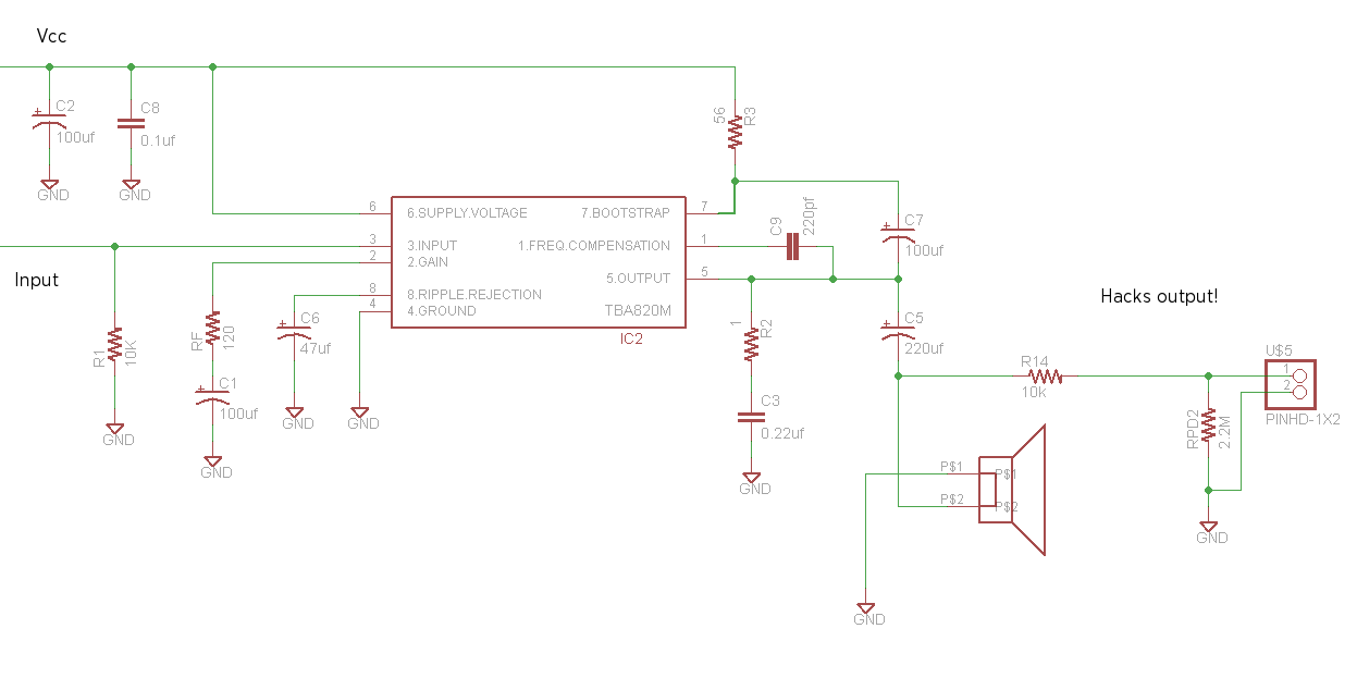
This is the back end. It's exactly the same as the schematic from the datasheet above. Except for the hacks output.
I wanted to make it easy to add something like a headphone output or an external speaker output or a line out or something similar. To do any of those things you have to decide what you want to do, figure out what additional external components you will need, and then calculate the appropriate value of R14.
The supplied value of R14 is 10k. With a 10k output volume potentiometer, you could hook up the Stella amp to a regular guitar amplifier and use it as a distortion pedal.
I'll have more examples of what you can do (with schematics) up on my mods page when I'm done writing it.