Click on any image to make it full size!
|
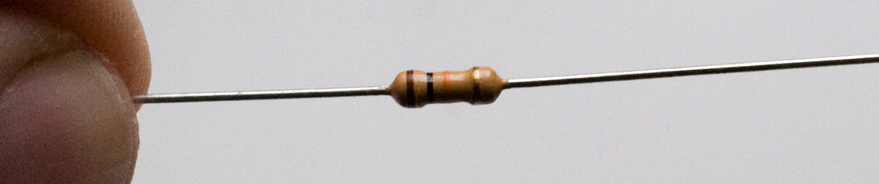
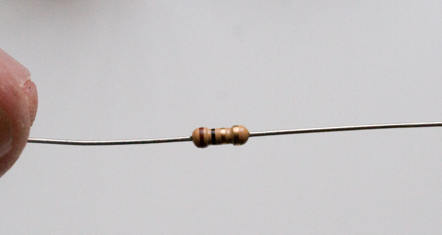
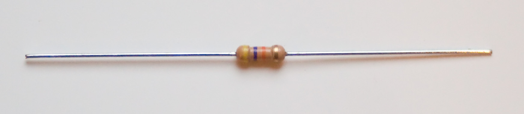
First, we're going to place R1. Find the 10k resistor. The color code on a 10k resistor will be brown-black-orange. |
|
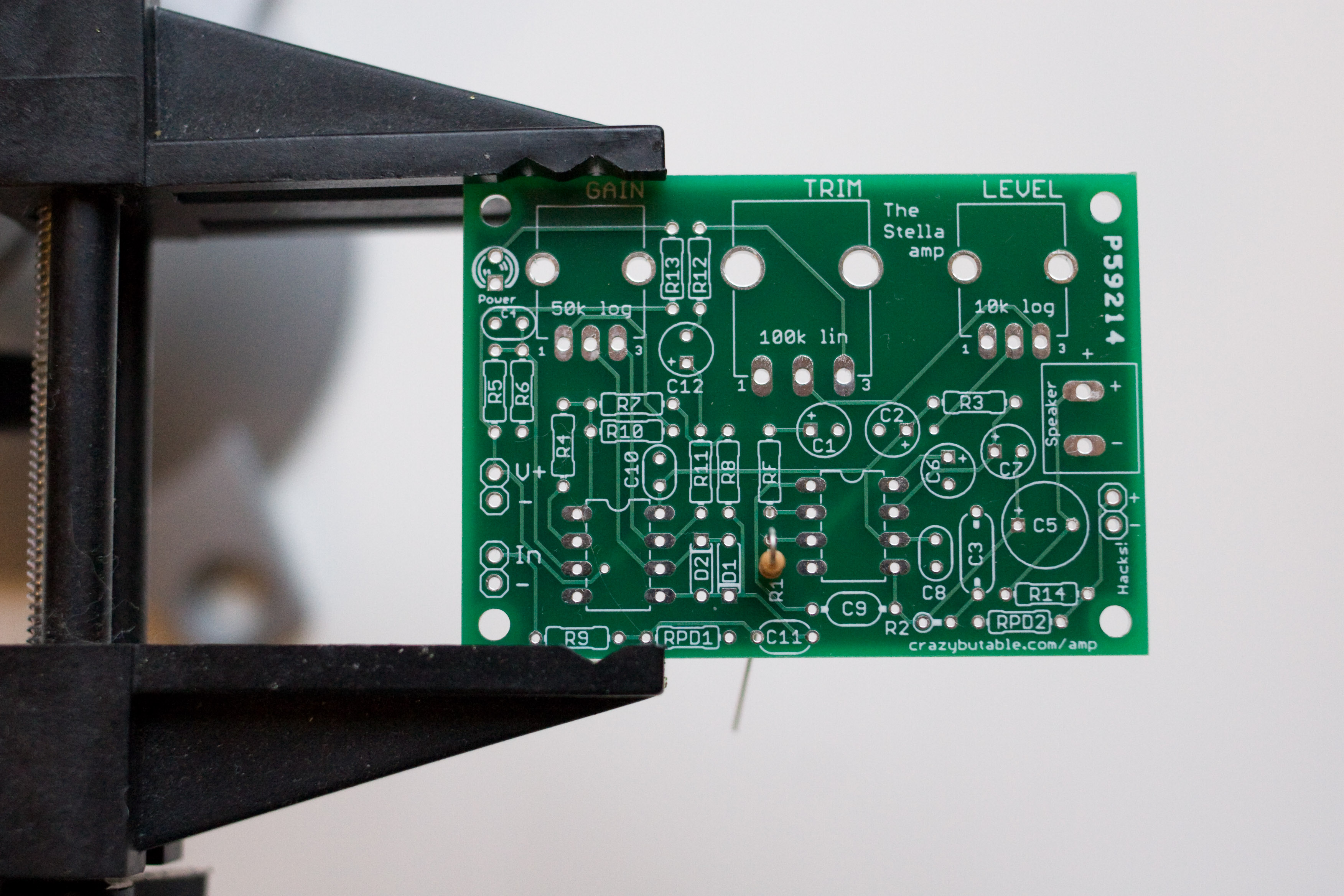
Bend it vertically and place it on the board. Although it is symmetrical and can go in either way, you should line up the body of the resistor with the silkscreen on the board. Bend the leads outward, then flip the board over. |
|
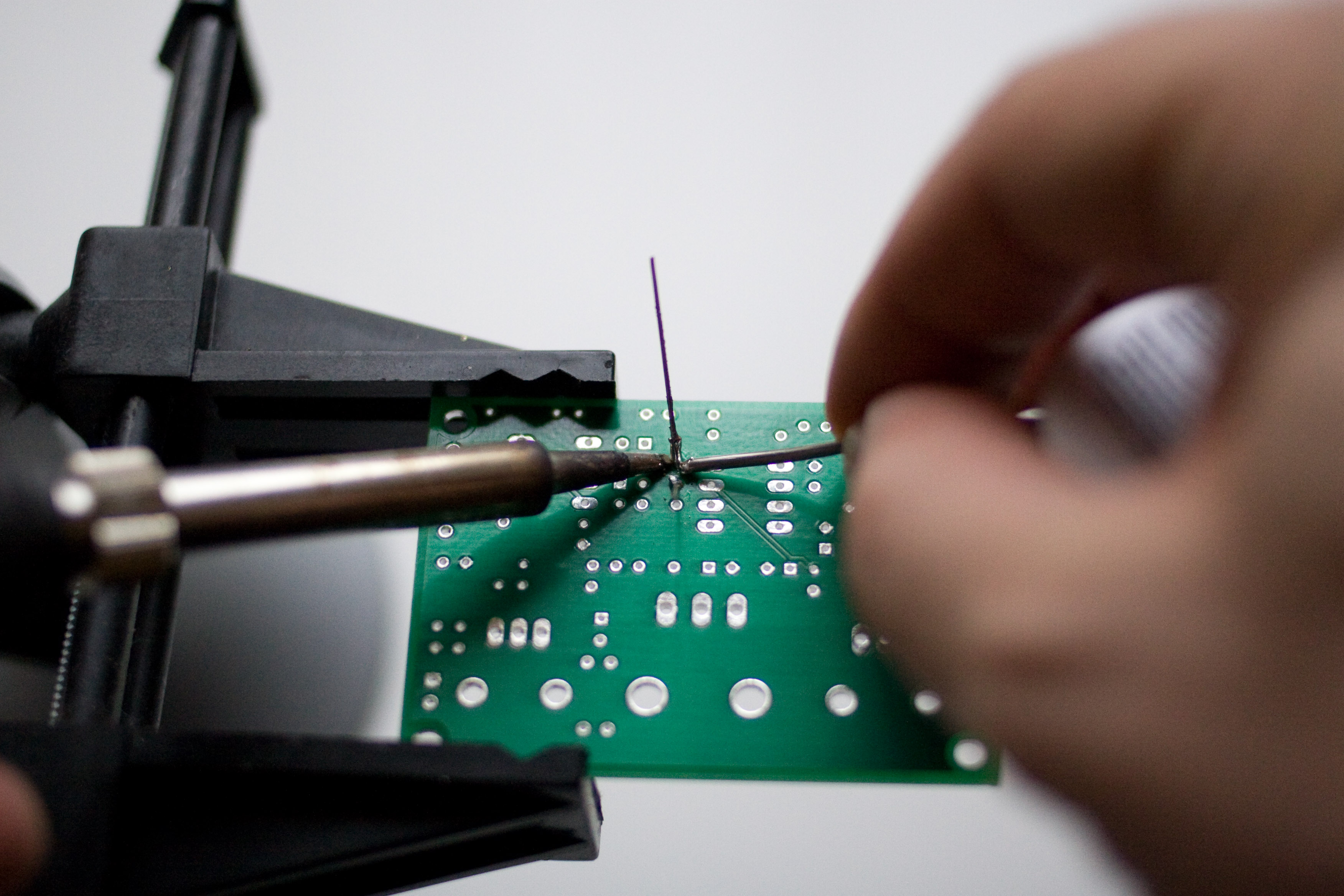
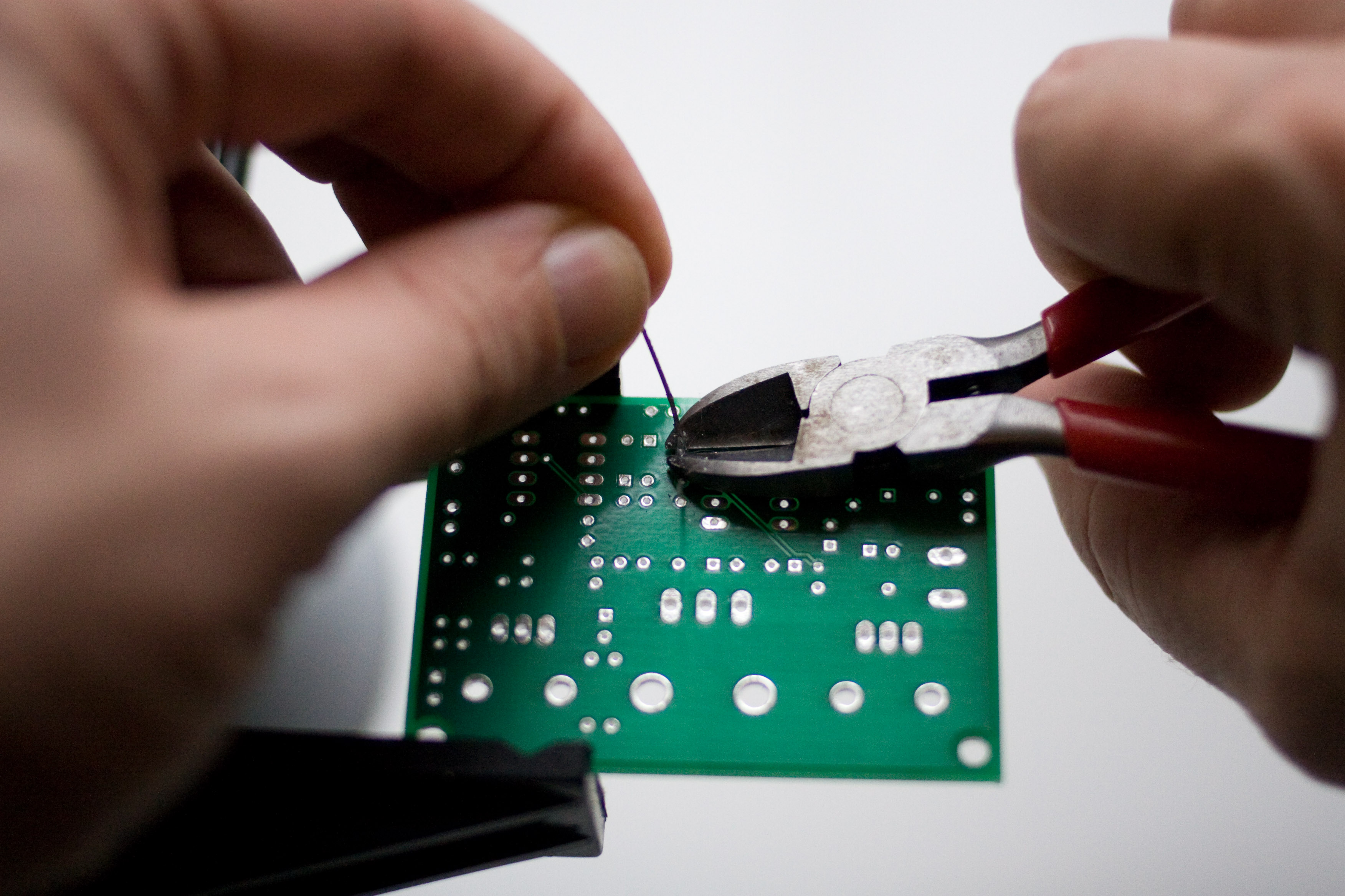
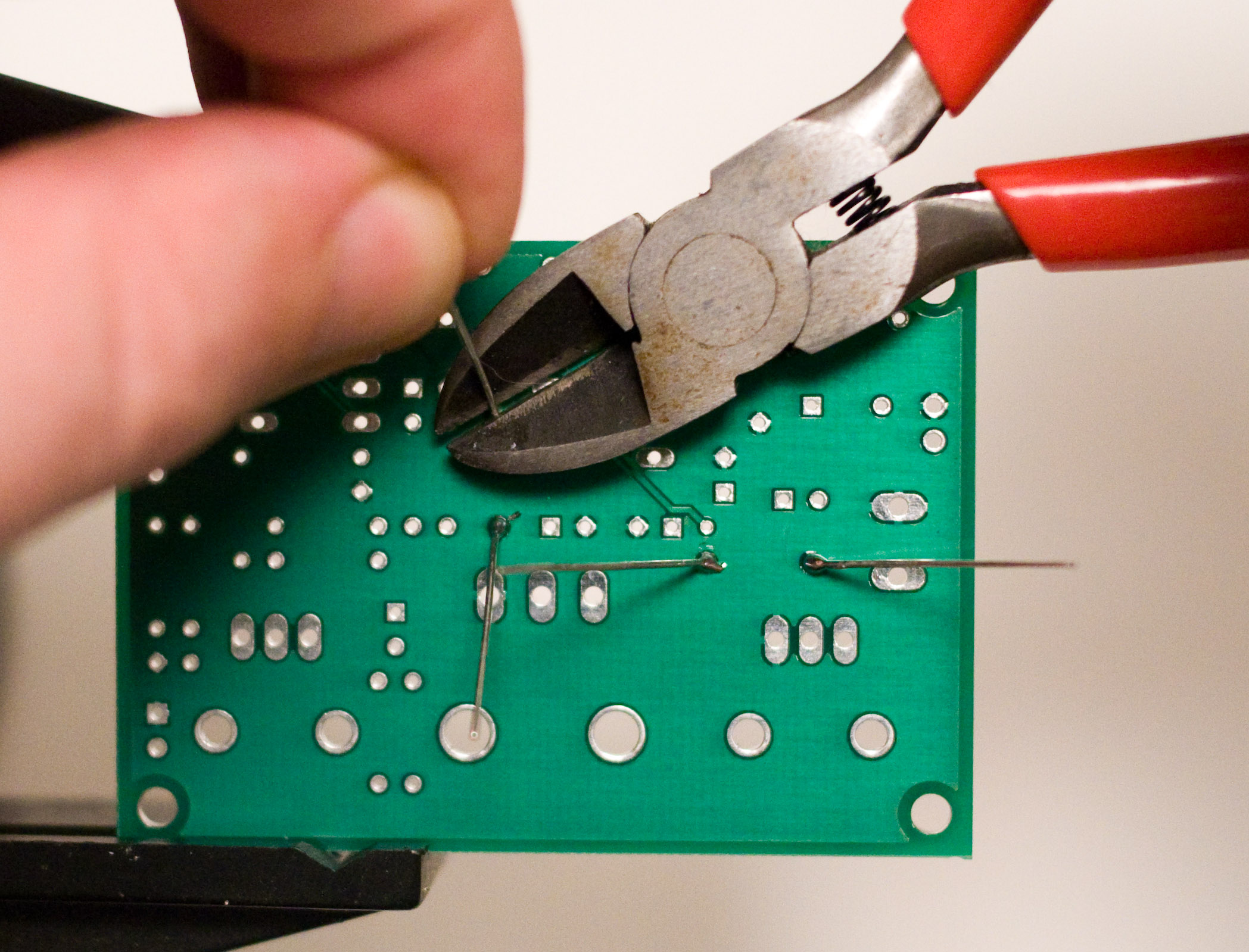
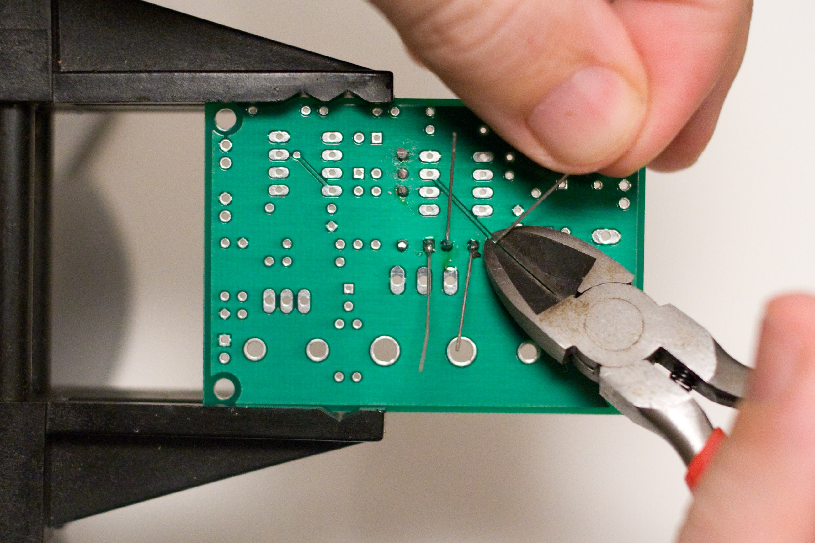
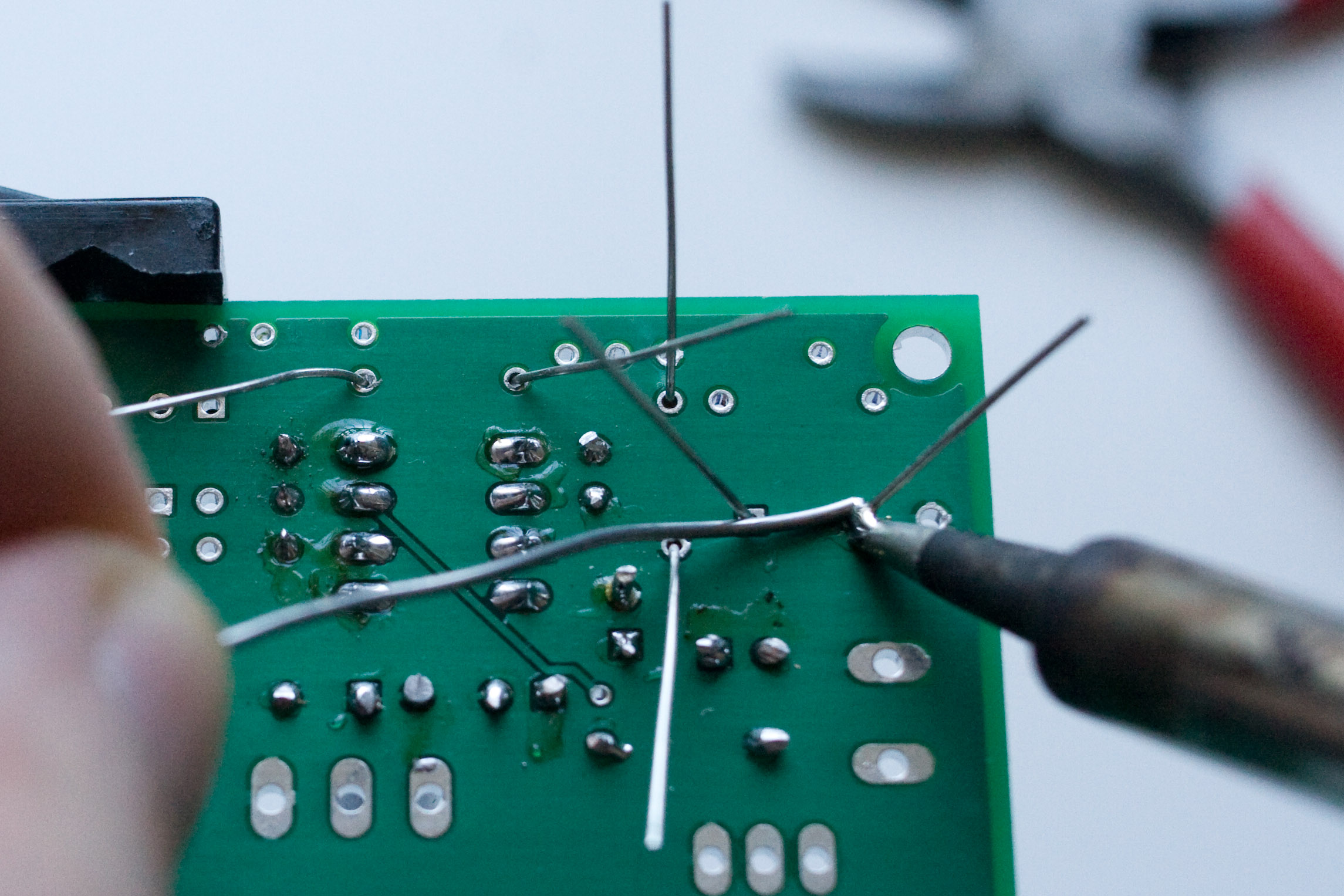
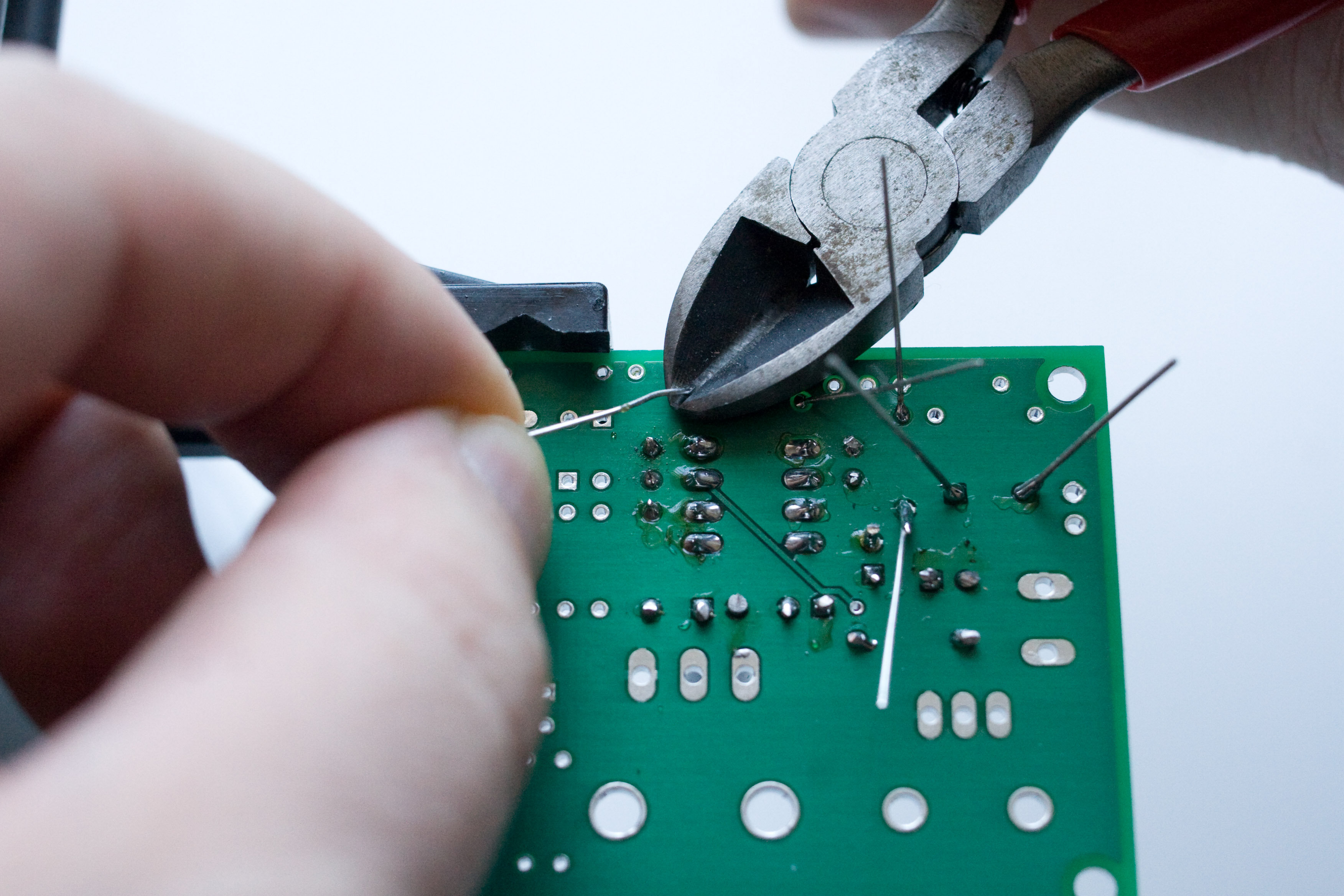
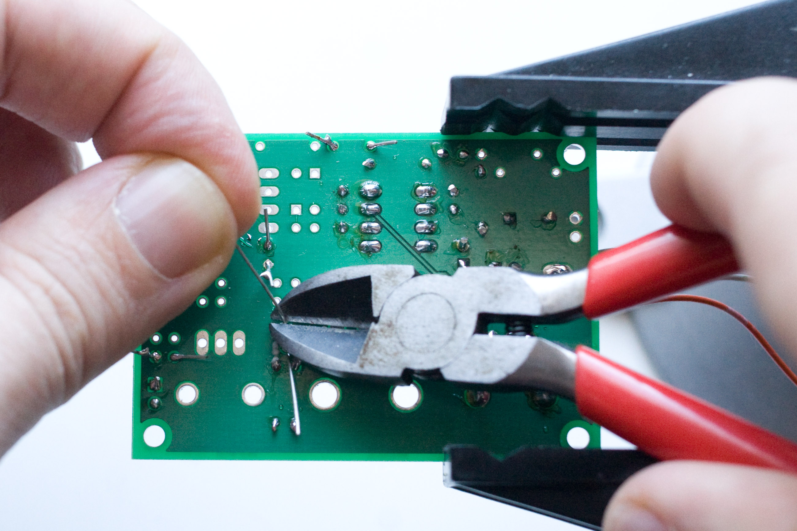
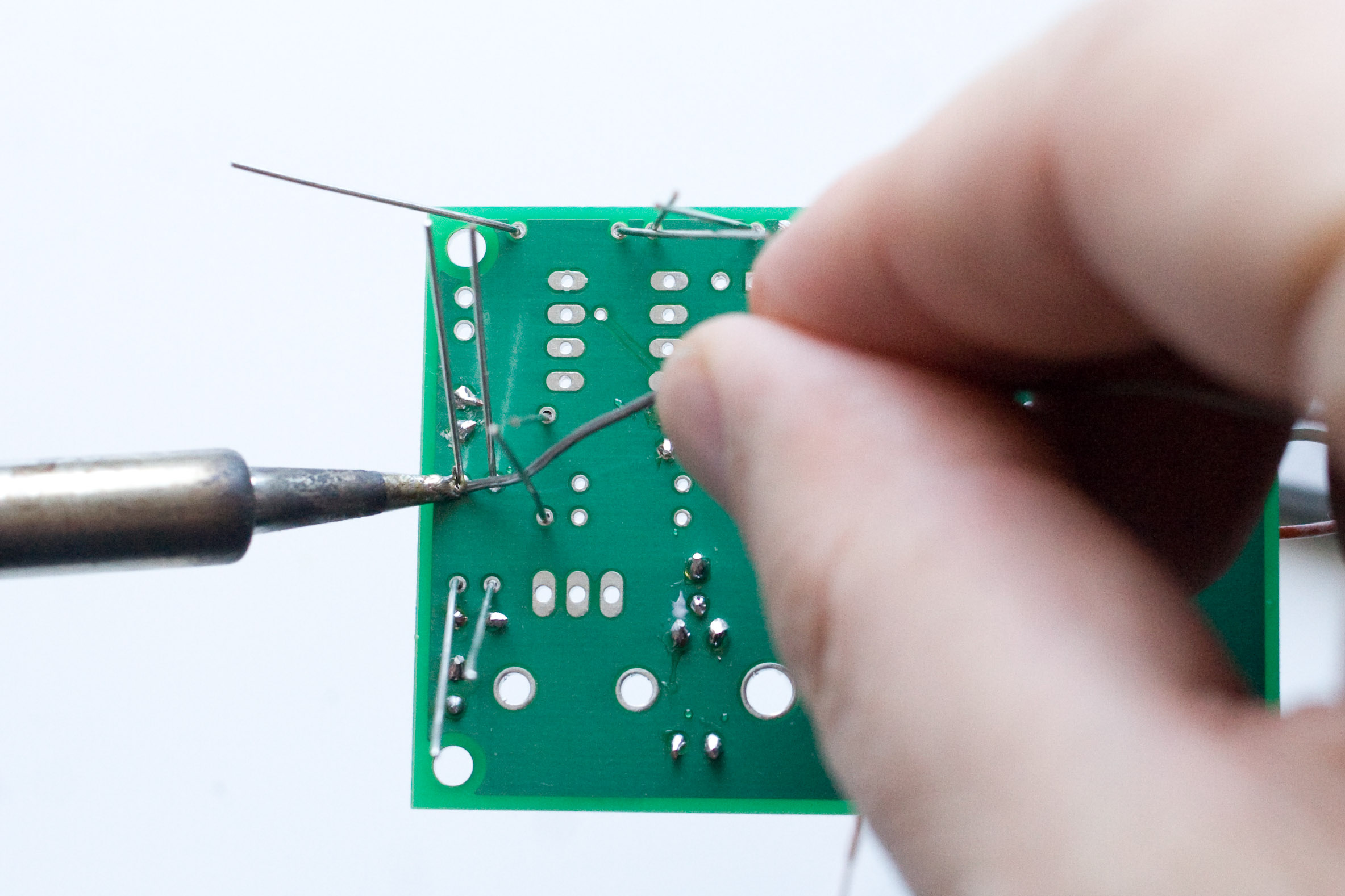
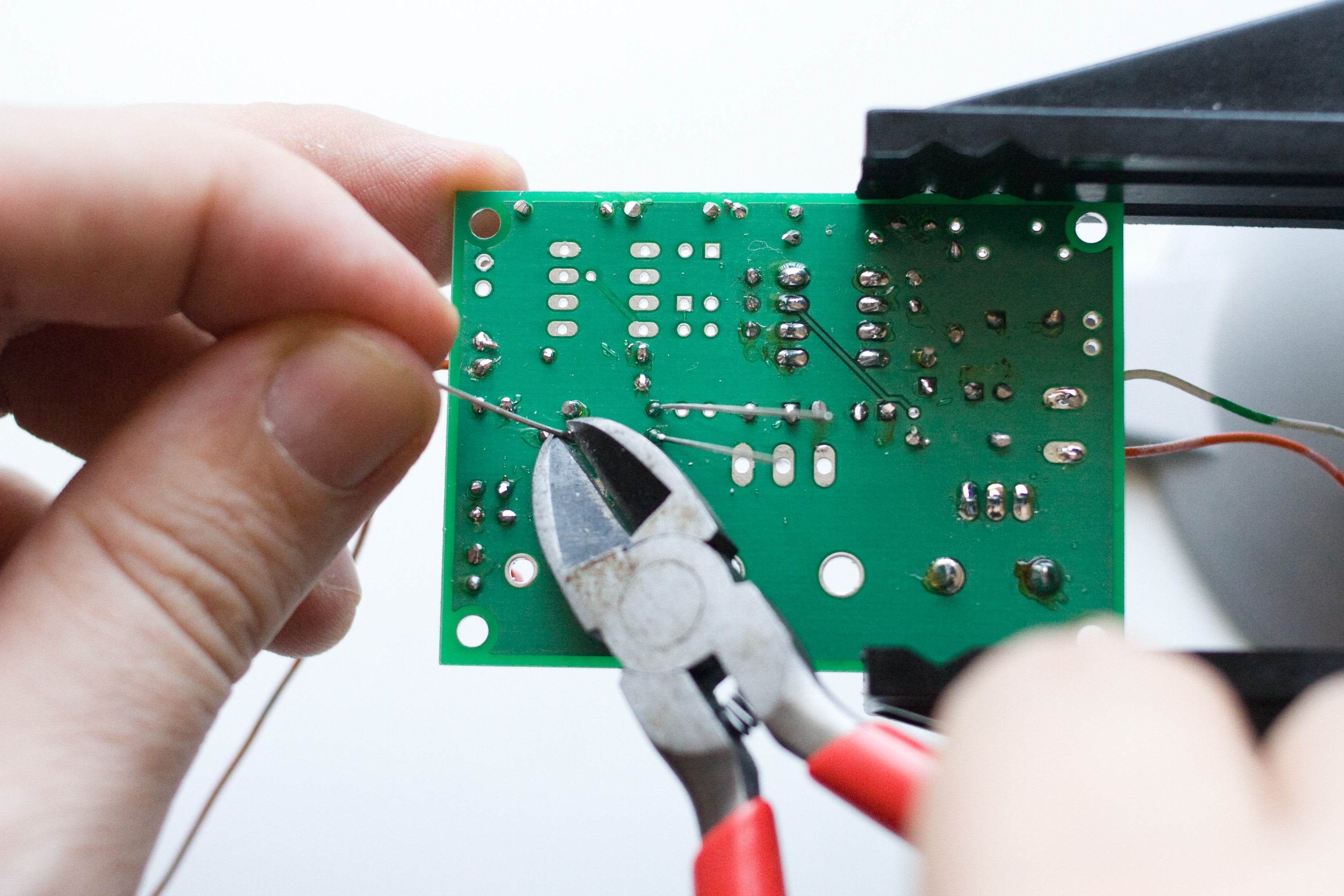
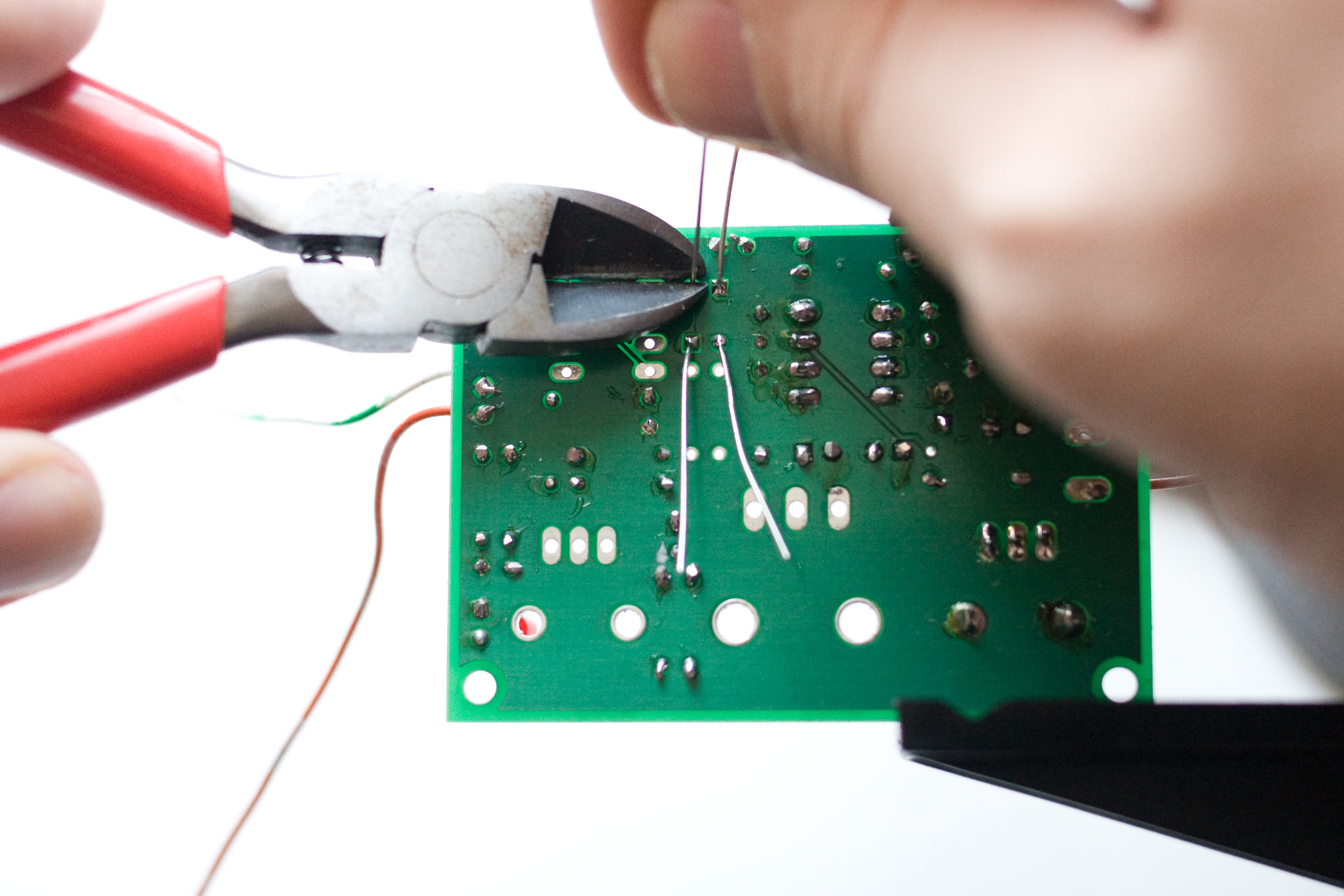
Solder and clip the leads. |
|
Make sure when you clip the leads you hold on to the other end. Otherwise, that little piece of metal will fly off into your eye, or your computer's power supply, or your floor, where you will promptly step on it and embed it into your foot. (Two of these three things have happened to me!) |
|
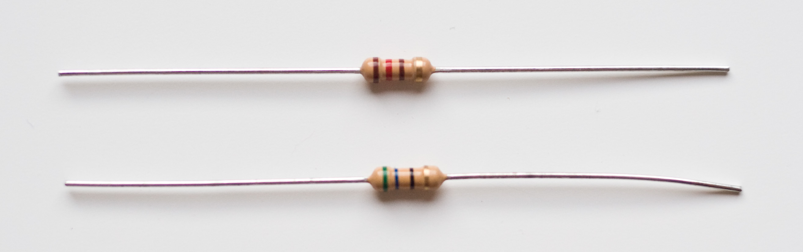
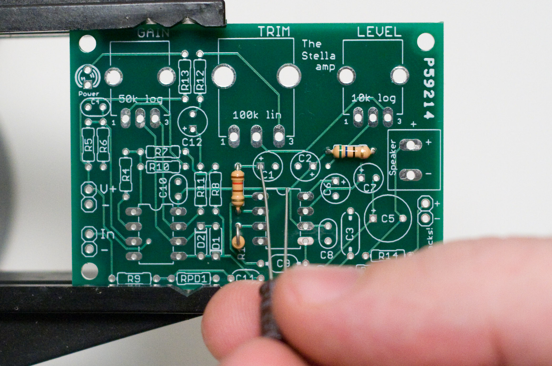
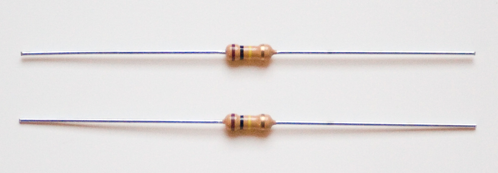
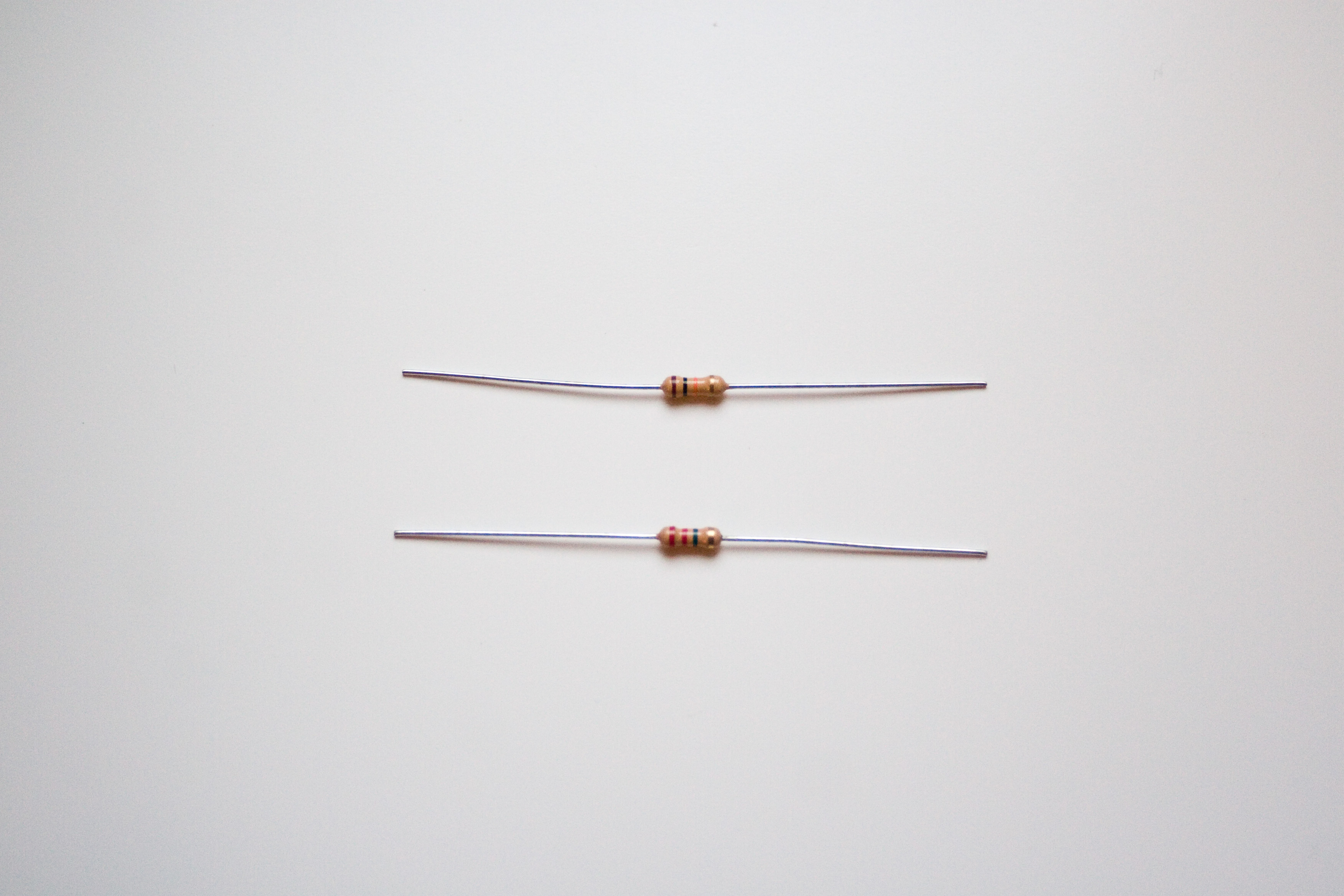
The next two resistors are Rf and R3. Rf (in conjunction with C9) sets the gain of the power stage, and is 120 ohms (Brown Red Brown) R3 is 56 ohms (Green Blue Black, click the image to view it full size if you can't see). R3 is part of the power stage. Make SURE you get the right value for R3! There is another resistor in the kit that is 560 ohms, which is Green Blue Brown, but this is not what you want here. You want Green Blue Black. Measure with a digital multimeter if you aren't sure. |
|
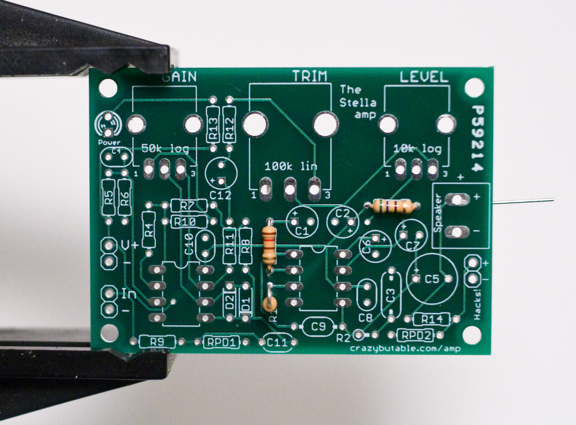
Bend those resistors like staples and stick them in the proper locations on the board. When you're done, it should look like this. |
|
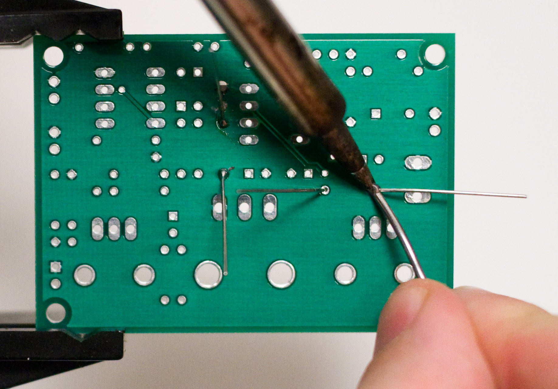
Flip the board over and solder and clip the leads. |
|
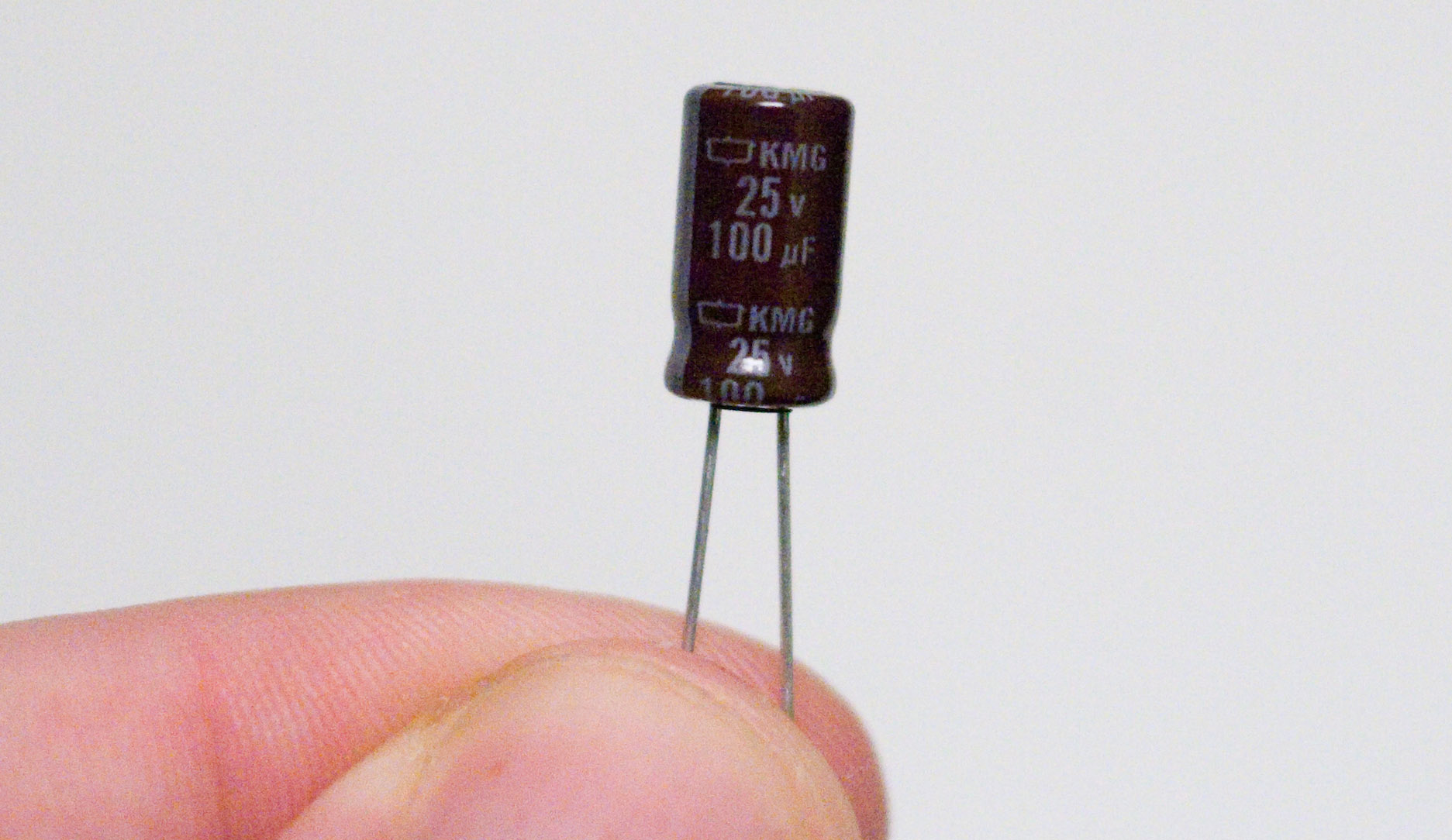
Next, find two of the 100uf electrolytic capacitors. We're going to place C1 and C2. C1 is part of the amplifier gain circuit, and C2 is going to provide power smoothing for output voltage spikes. |
|
Electrolytic capacitors are polarized, which means that they can only go in one way. If you put them in backwards they will fry themselves. One lead is longer than the other. The longer lead is the + lead and should go into the + hole on the board, like so. |
|
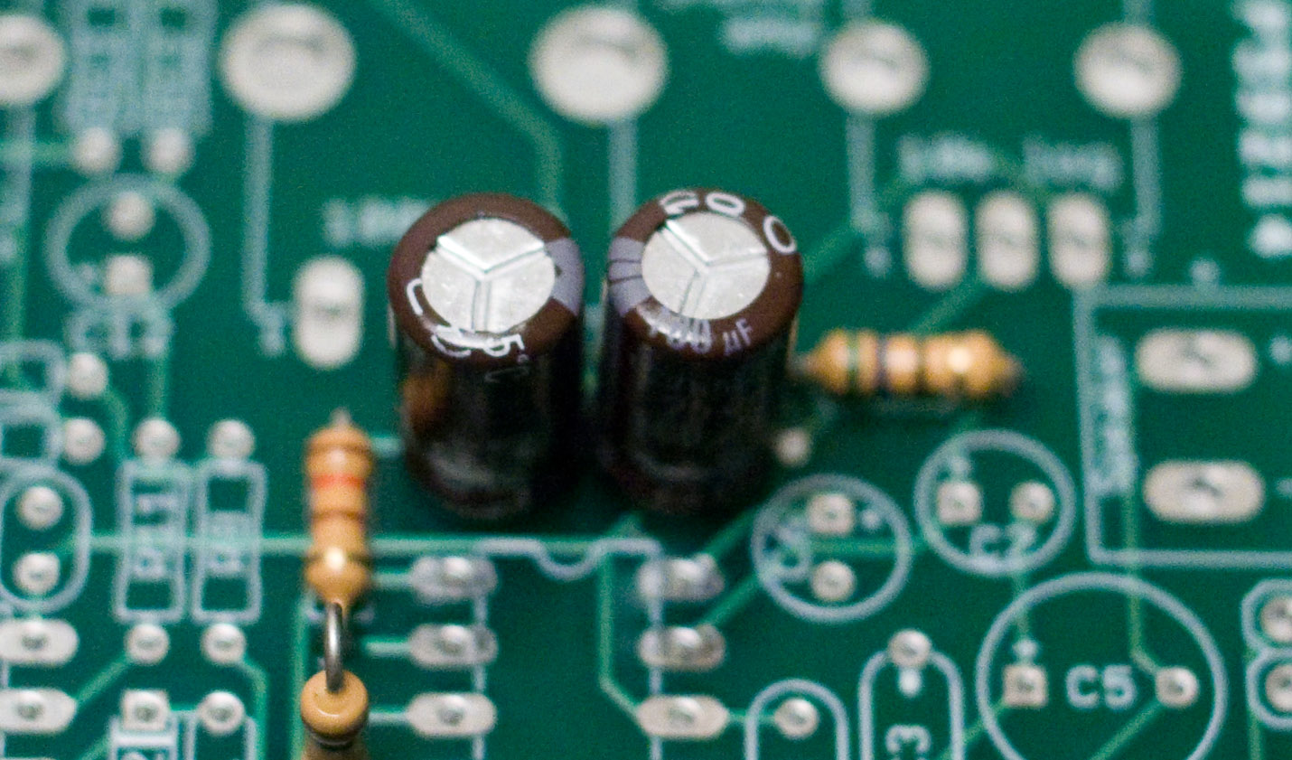
Electrolytic caps also frequently have a strip along the side which marks the negative side. As you can see here, the negative sides of C1 and C2 are facing each other. Make sure you double check your connections and get these capacitors placed properly, because if you get this wrong you will damage your kit. |
|
Solder and clip the leads! |
|
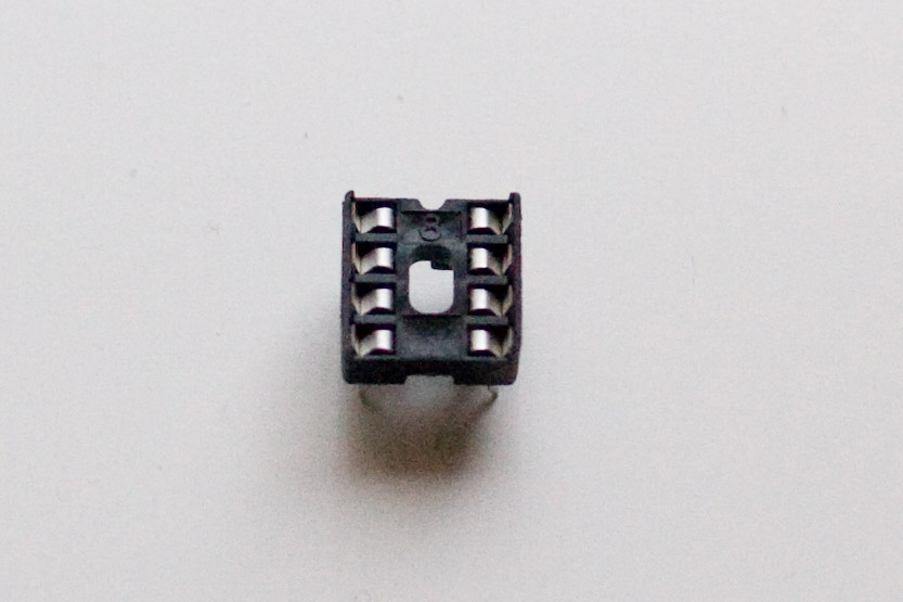
Now we're going to place one of our DIP sockets and one of our decoupling capacitors. Find a DIP socket. Notice the notch on top. Line up the notch on top to the notch on the silkscreen on the board. Although you can put the DIP socket in upside down and have everything work out electrically, you really should make sure it's "right side up." Otherwise it will be confusing when you put the chip in because you'll have to remember that the DIP socket is "backwards". |
|
The DIP socket should snap into place. |
|
Next, find C8, a 0.1 microfarad capacitor. This capacitor will help provide high freqency filtering and power supply isolation for our power amplifier chip. Place it on the board and bend the leads outward. |
|
Although the socket will stay in place when you turn the board upside down, if you want it to remain flush with the board while soldering you can hold it in place with your finger, like so. You can also use tape. Be careful because you can burn yourself if the socket heats up too much while soldering. First solder two opposite corners. |
|
Then if you're happy with the positioning of the socket, solder the remaining pins. |
|
Solder and clip the leads on the capacitor. The leads on the DIP socket are short enough that you don't have to worry about clipping them. |
|
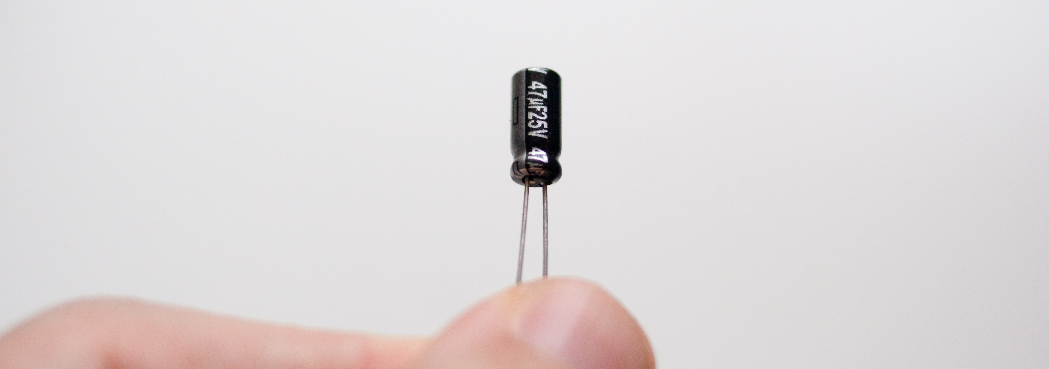
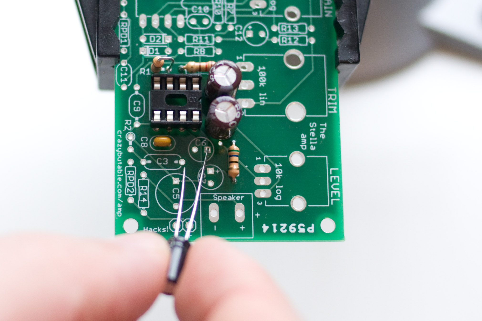
Now we're going to place two more capacitors in our amplifier circuit, C6 and C7. C6 is a 47uf electrolytic capacitor, and it looks like this. Please note that in some kits C6 will be blue instead of black. It is still the same size and will still say 47uf on the side, however. |
|
Place C6 on the board, and remember to check the polarity. The long lead is the + lead. |
|
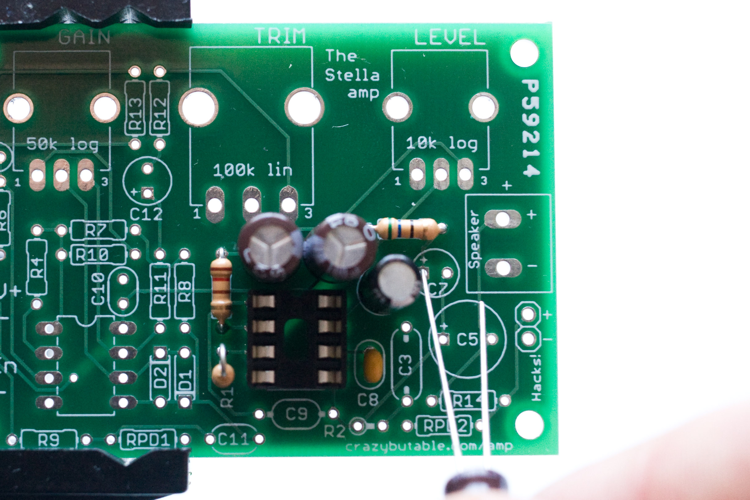
C7 is the last 100uF capacitor. This is part of the output circuitry for the amp. Watch your polarity when putting it in. |
|
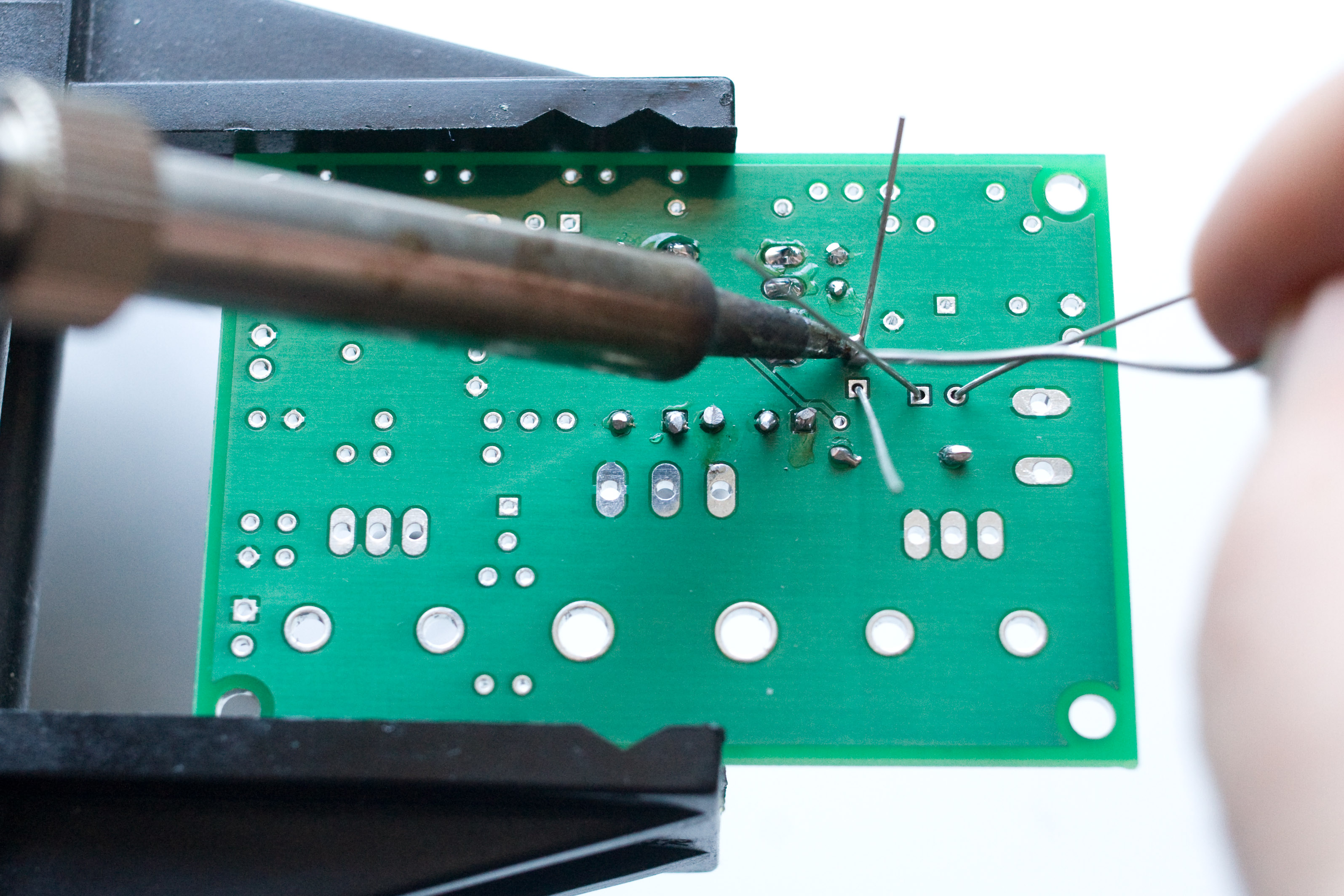
Solder and clip the leads. |
|
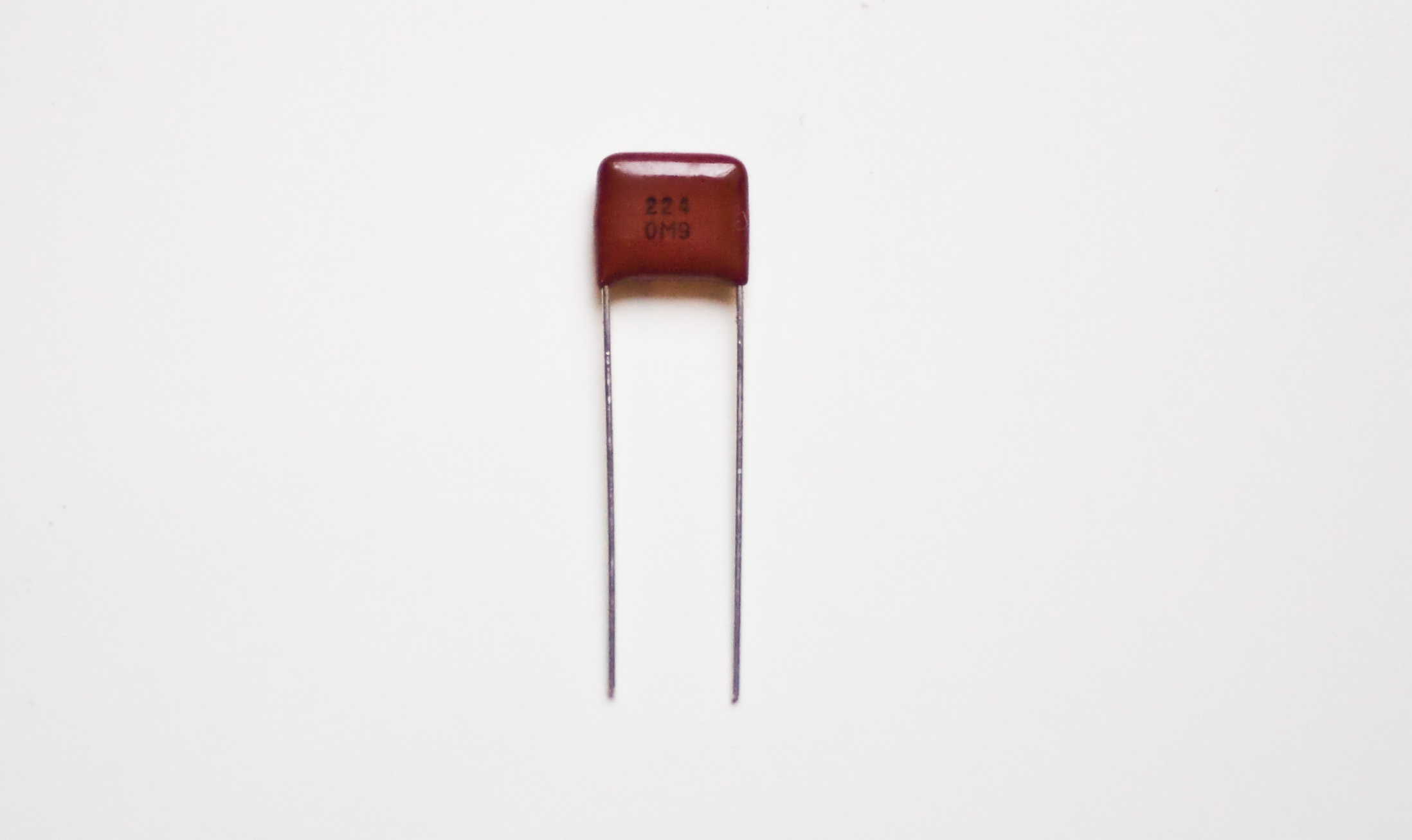
Find C3 and place it on the board. C3 is part of the output circuitry. I'm not exactly sure what it does but I'll figure it out someday. In the meantime, put it on the board and when it is in place, gently bend the leads outward. |
|
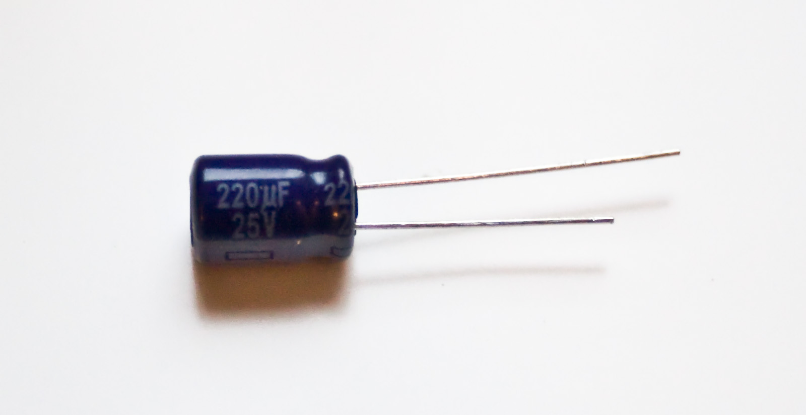
Find C5. C5 is a 220 uf electrolytic capacitor. This capacitor blocks the DC bias of the amplifier chip. It only goes in one way: make sure the long, positive lead of the capacitor goes in the hole marked with a +. |
|
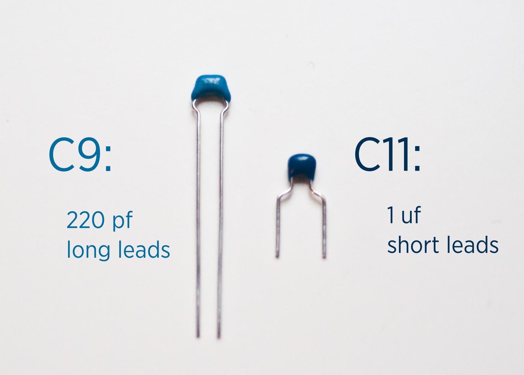
Next, find C9. C9 is the blue 220pf capactior. In this picture, it is the one on the left with the long leads. C9 sets the maximum output frequency of the amp. It is a ceramic capacitor and can be placed either way. |
|
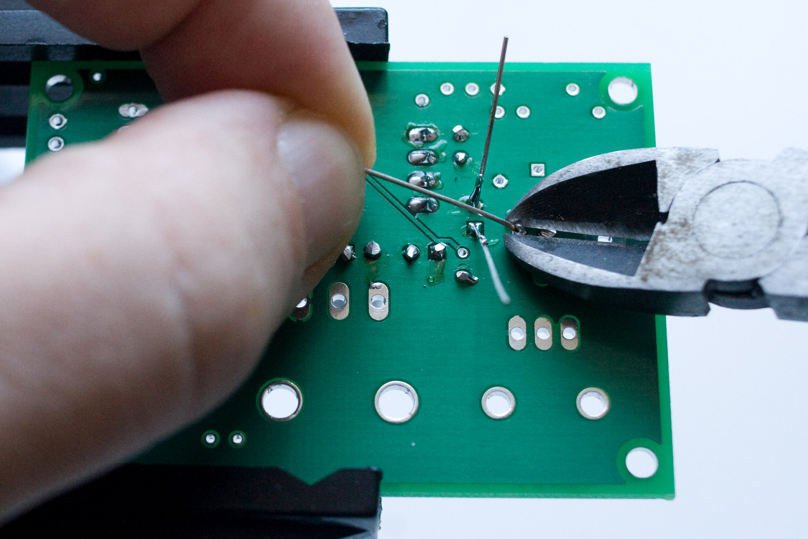
Solder and clip the leads of C3, C5 and C9. |
|
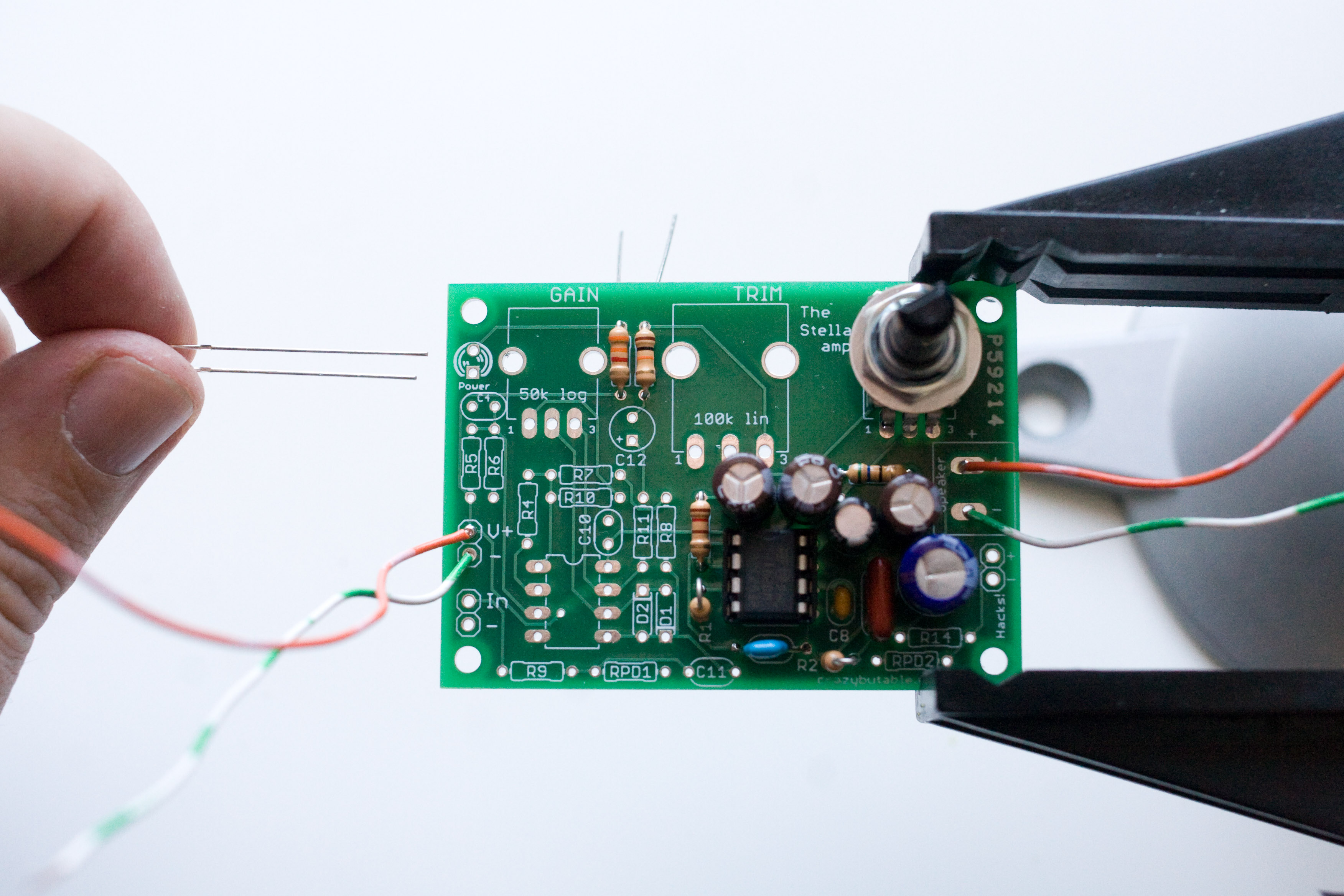
Now find R2. R2 is a 1 ohm resistor. The color code is brown black gold gold. |
|
Bend the resistor vertically and place it on the board like so. |
|
Solder and clip the leads. |
|
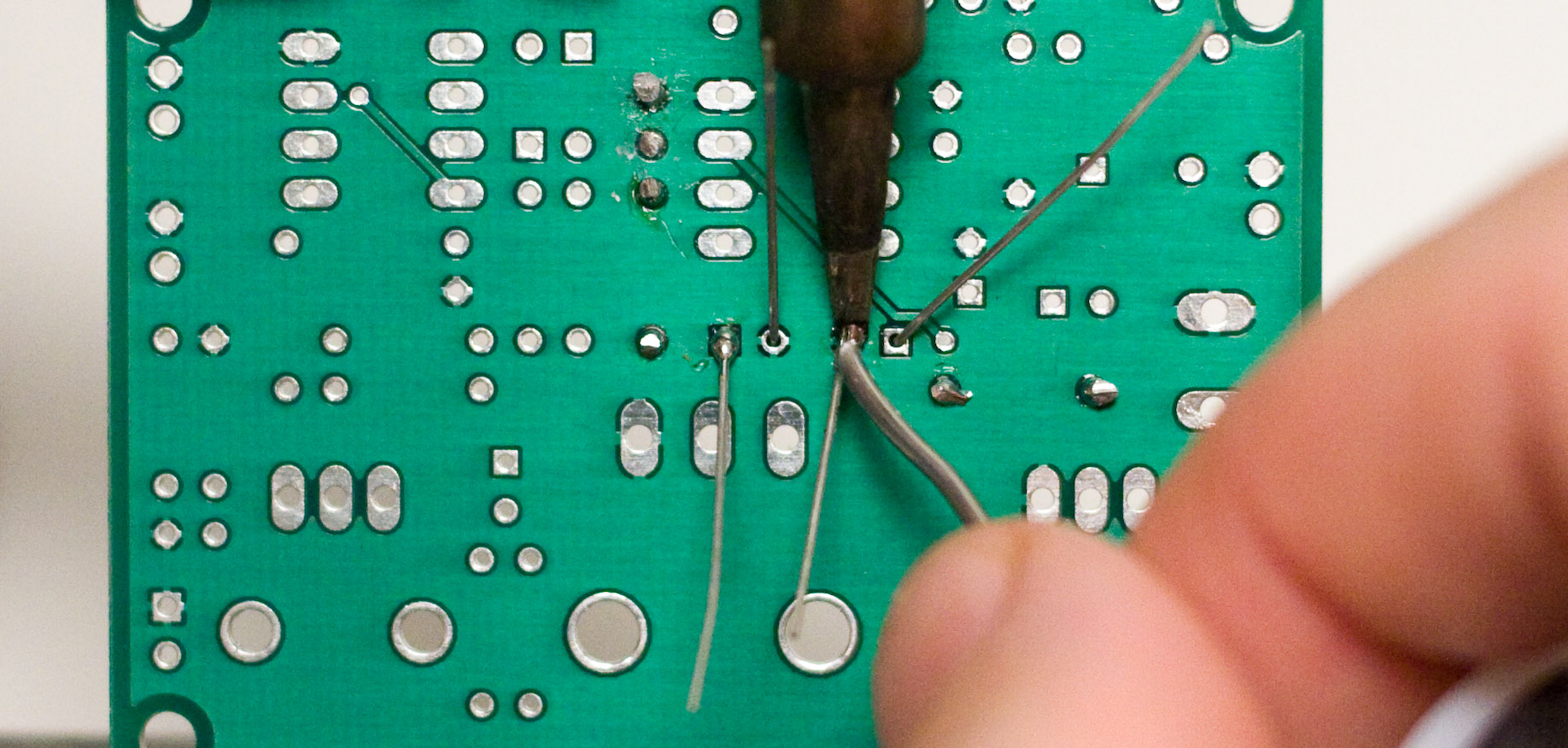
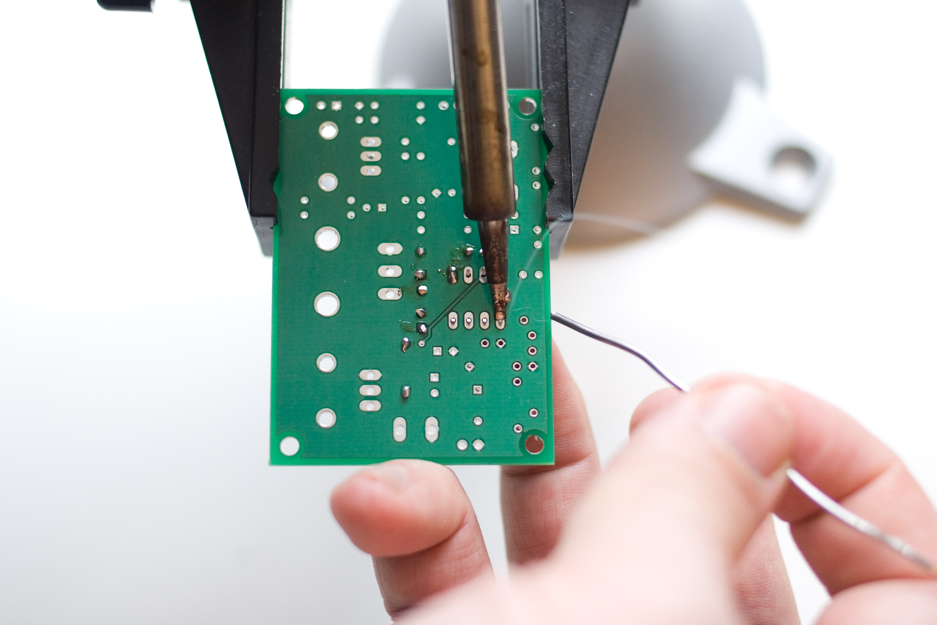
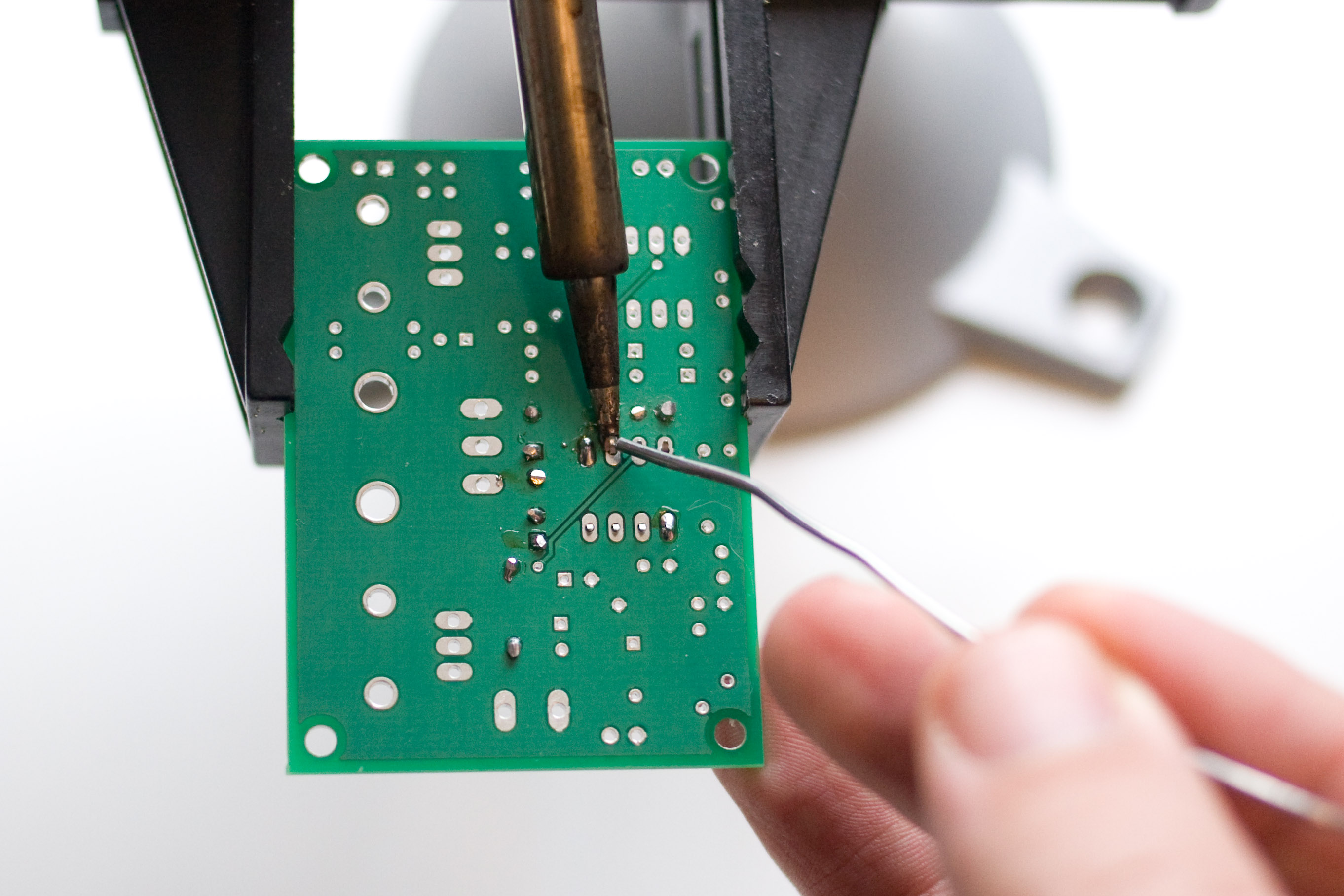
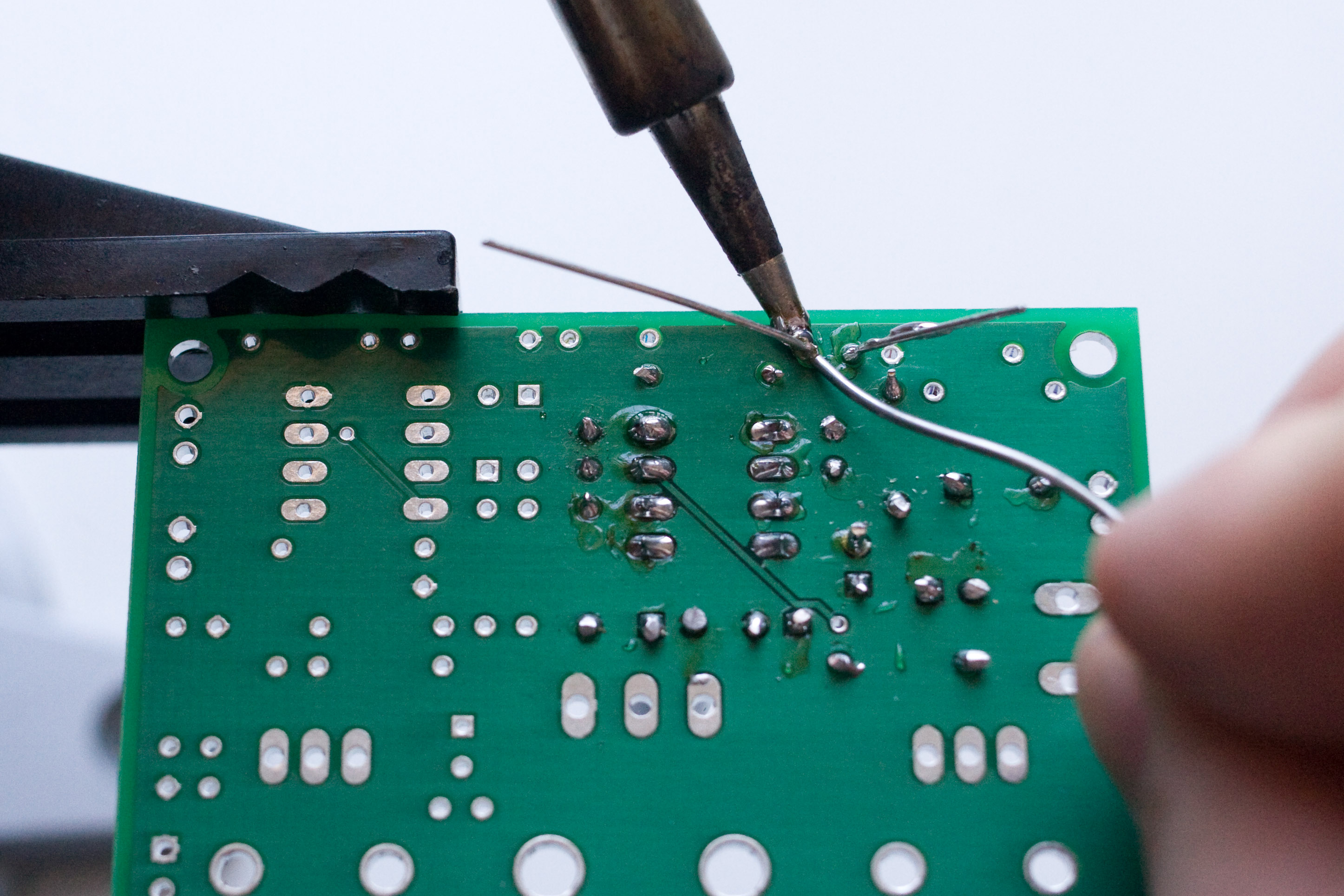
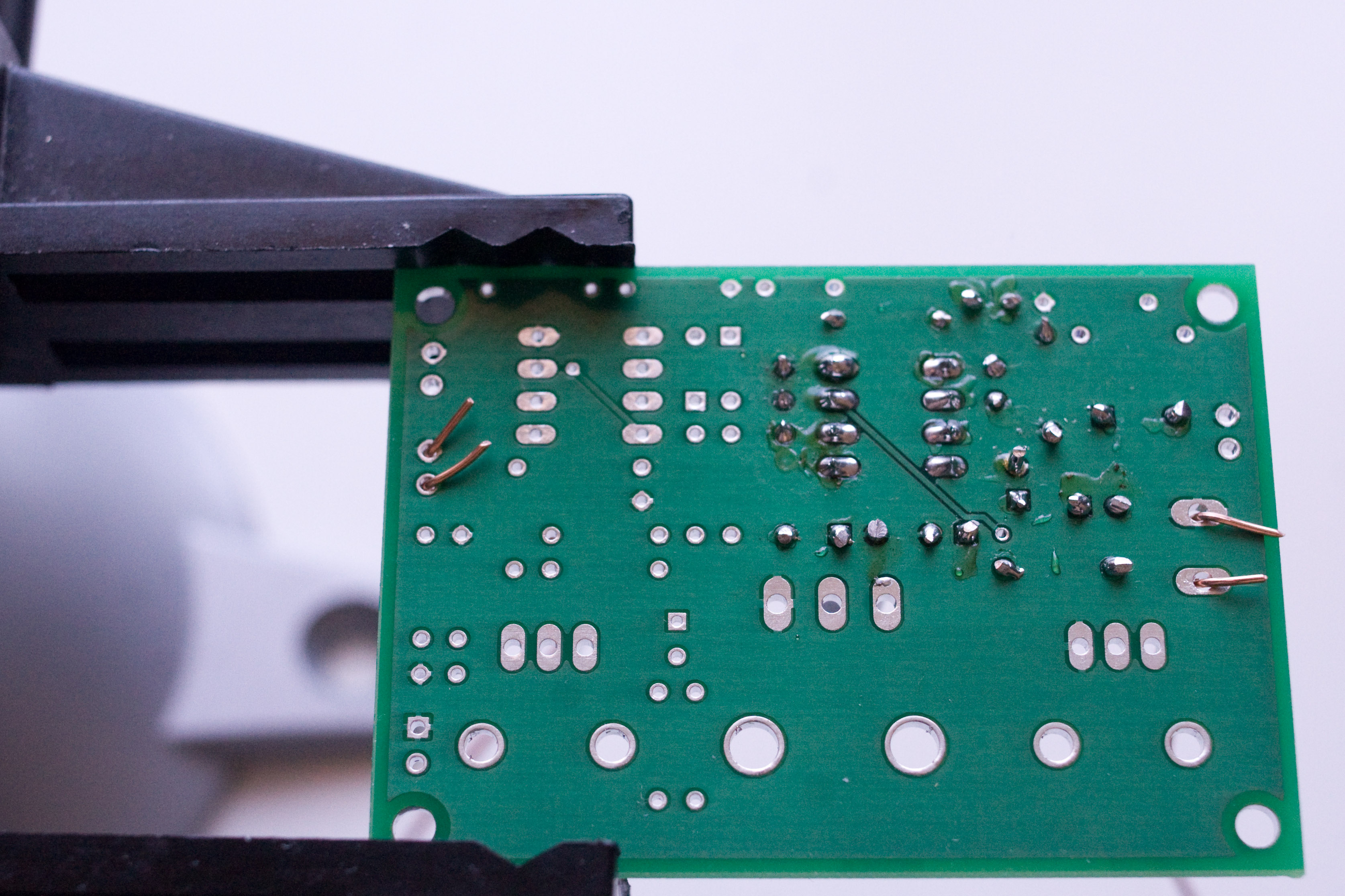
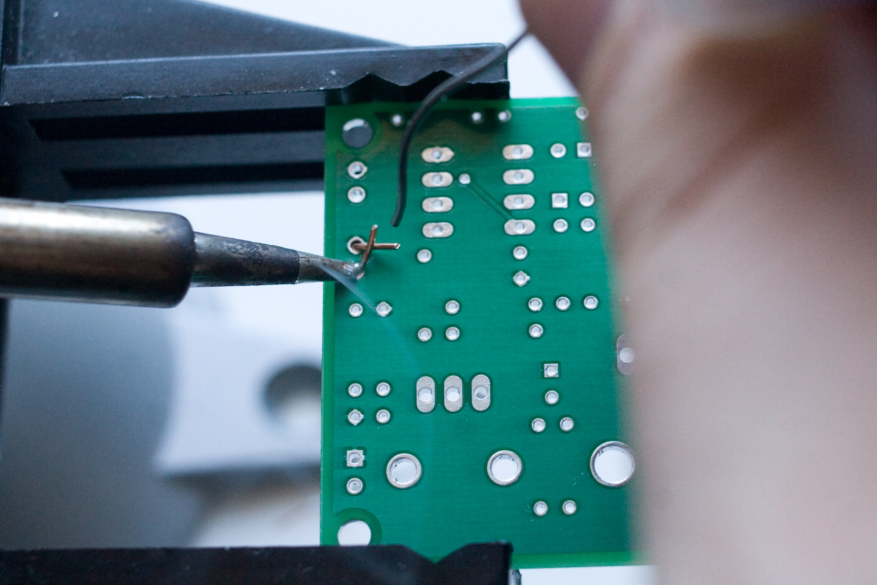
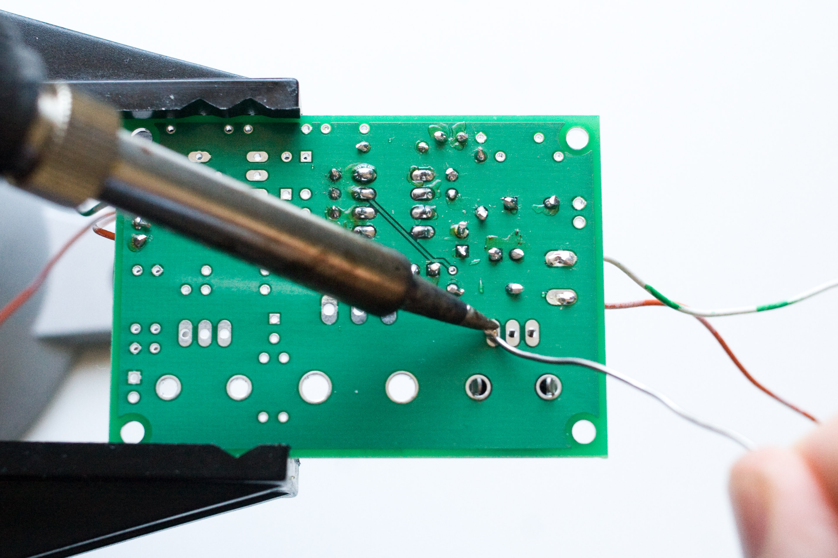
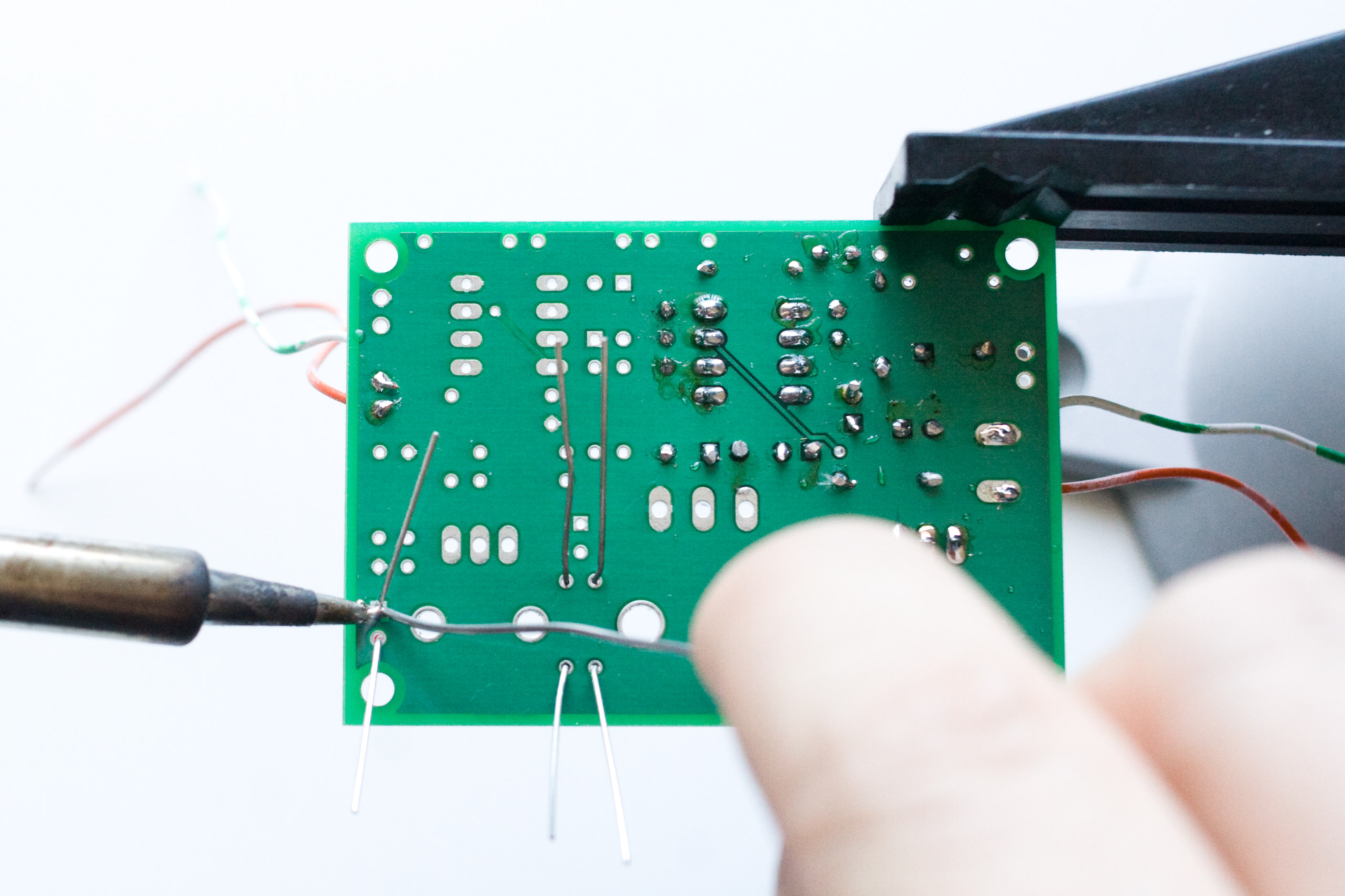
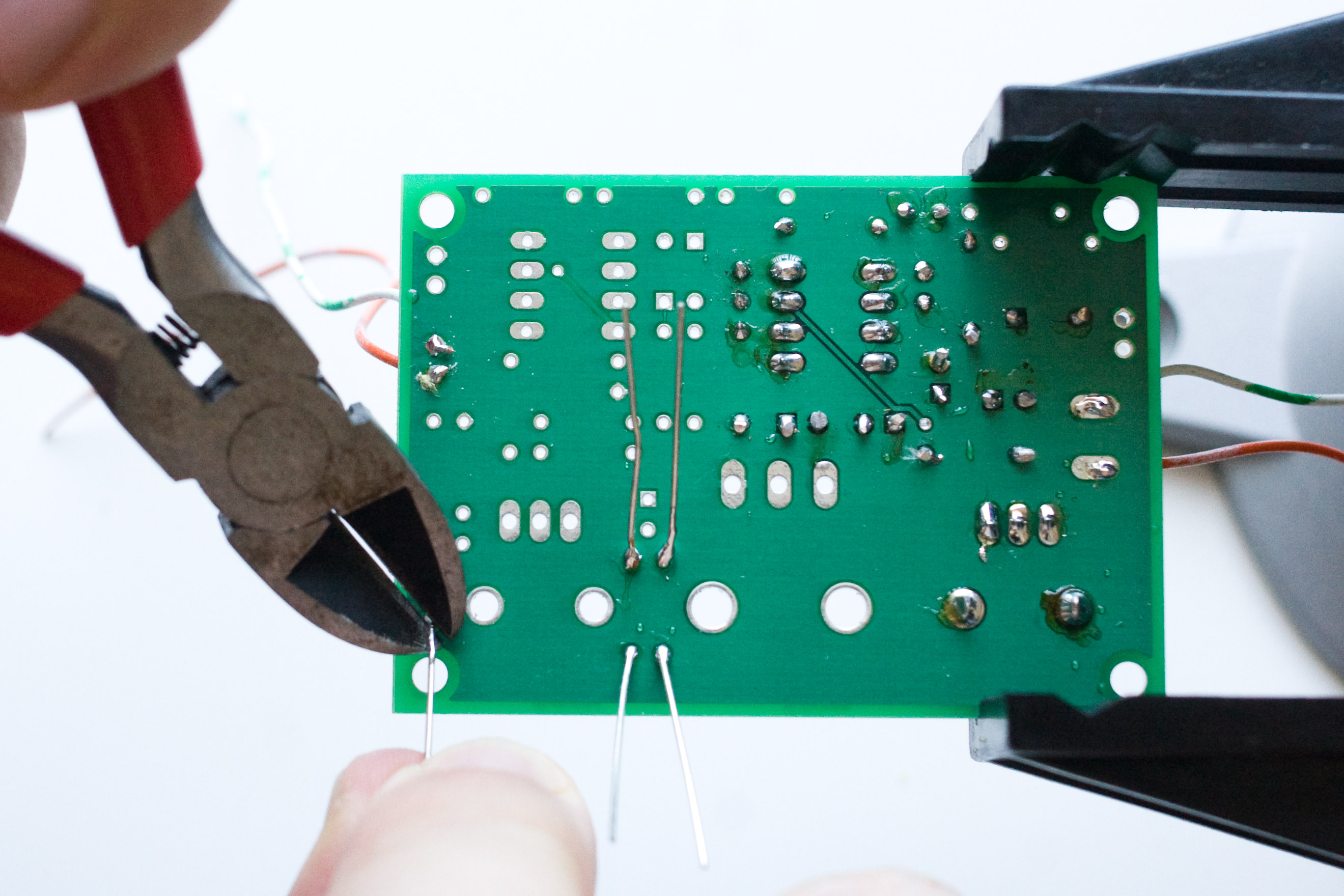
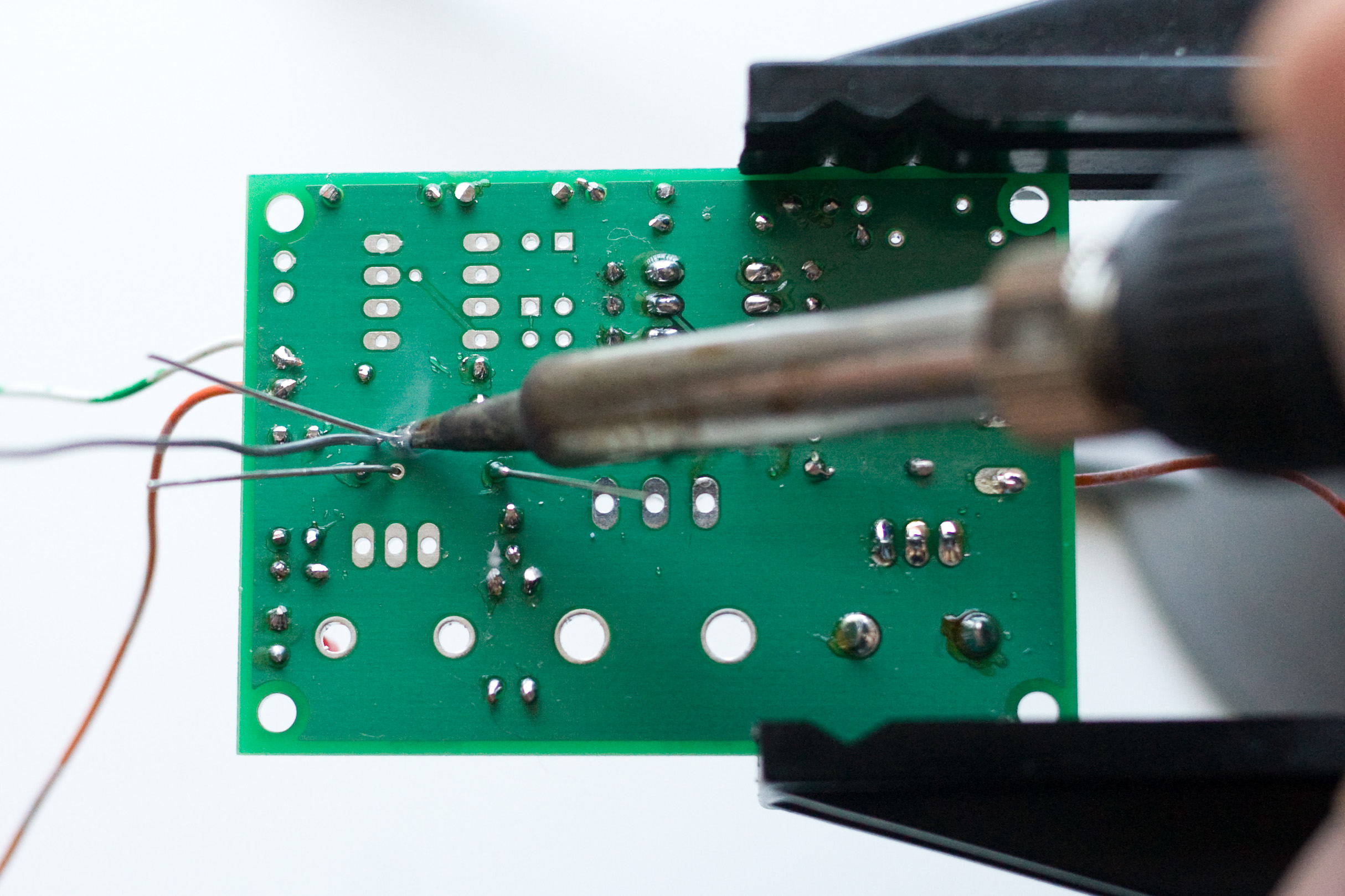
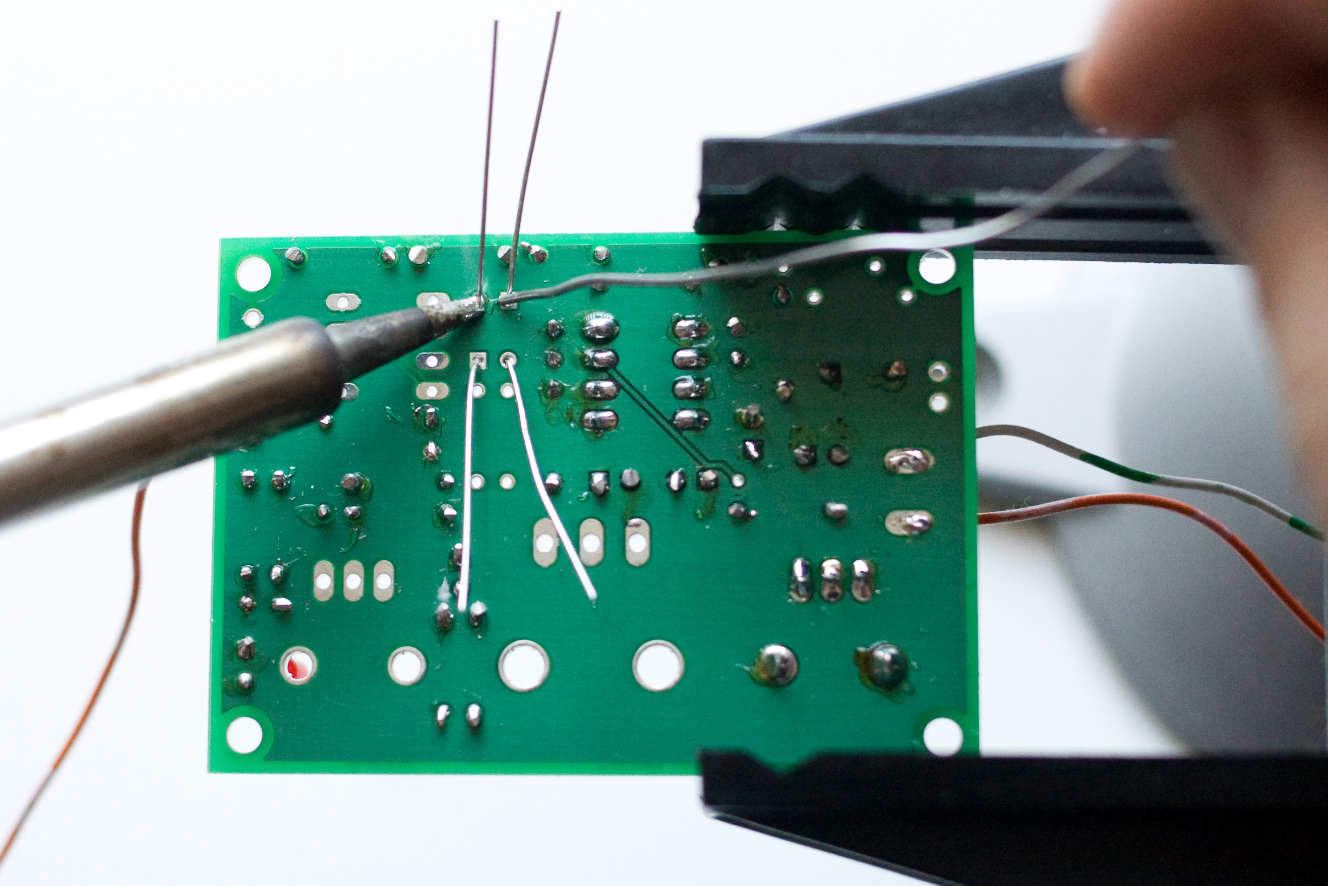
Time for some power and output wires! I just soldered in some scrap solid core bell wire that I had laying around. You can solder in your final connections here if you don't think it will make your board too unwieldly to work with. |
|
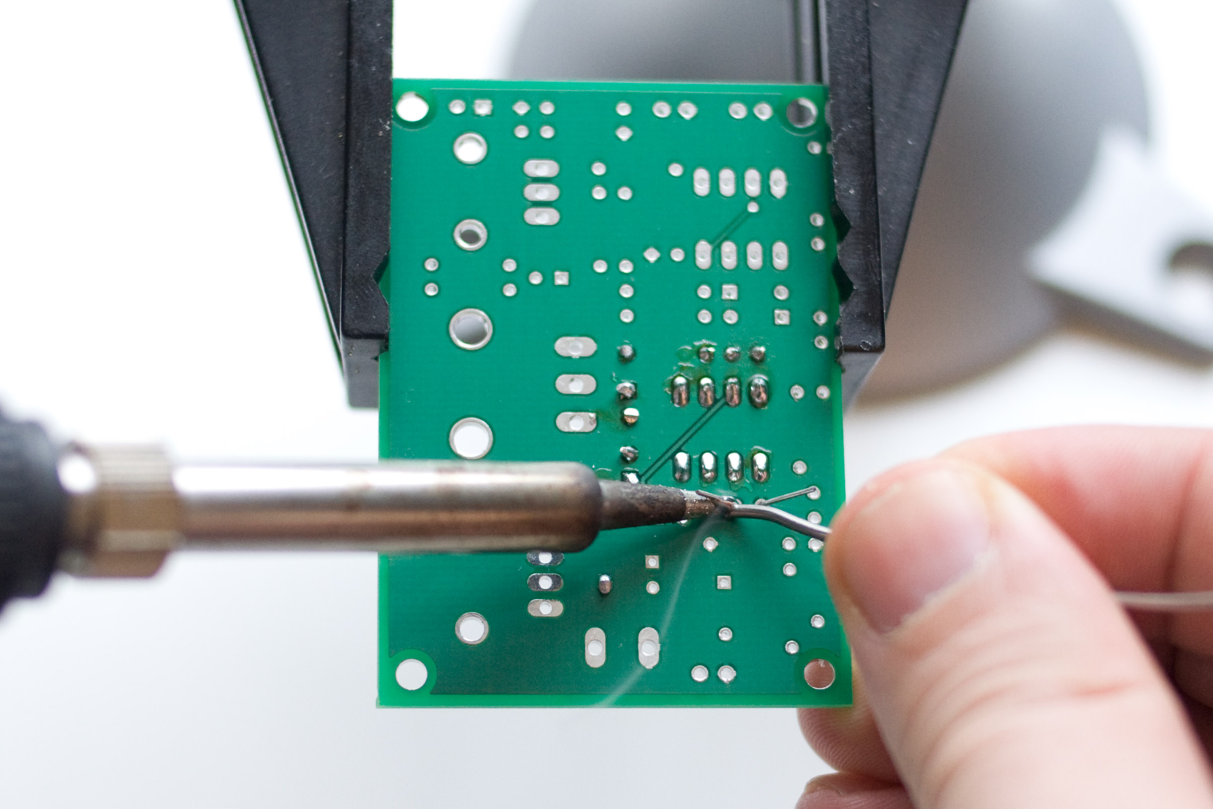
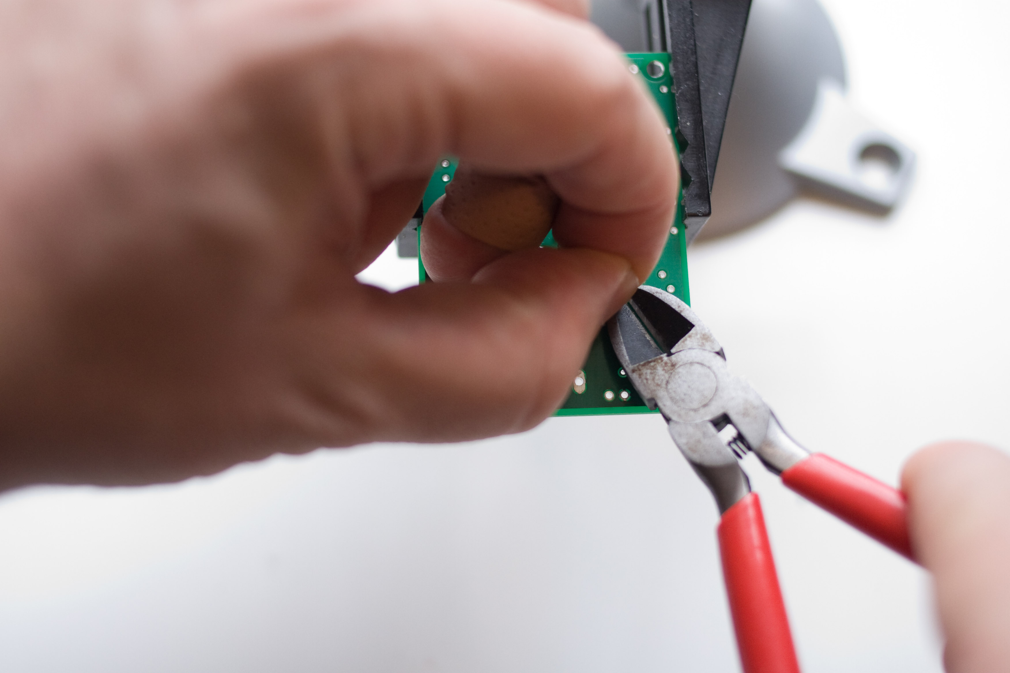
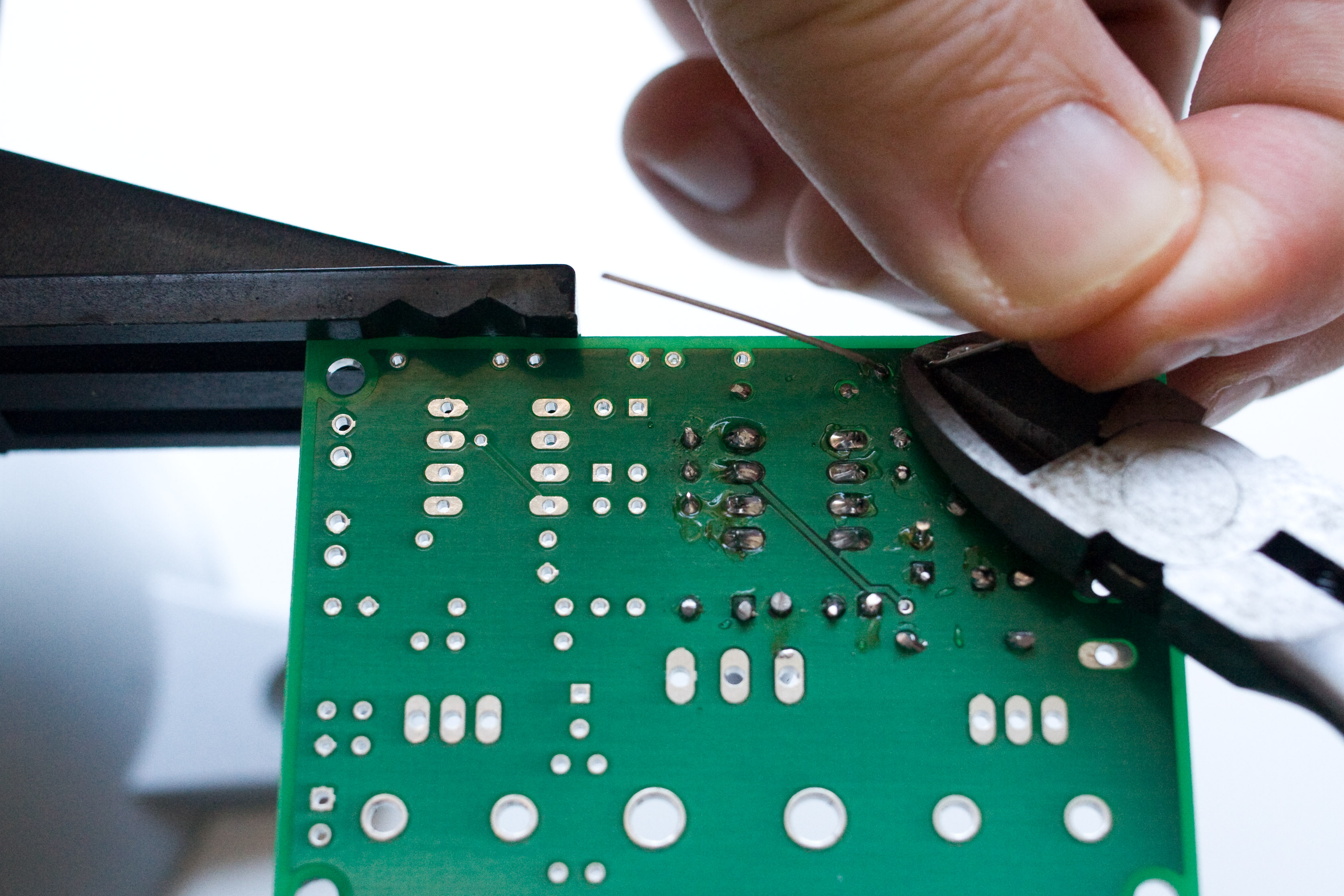
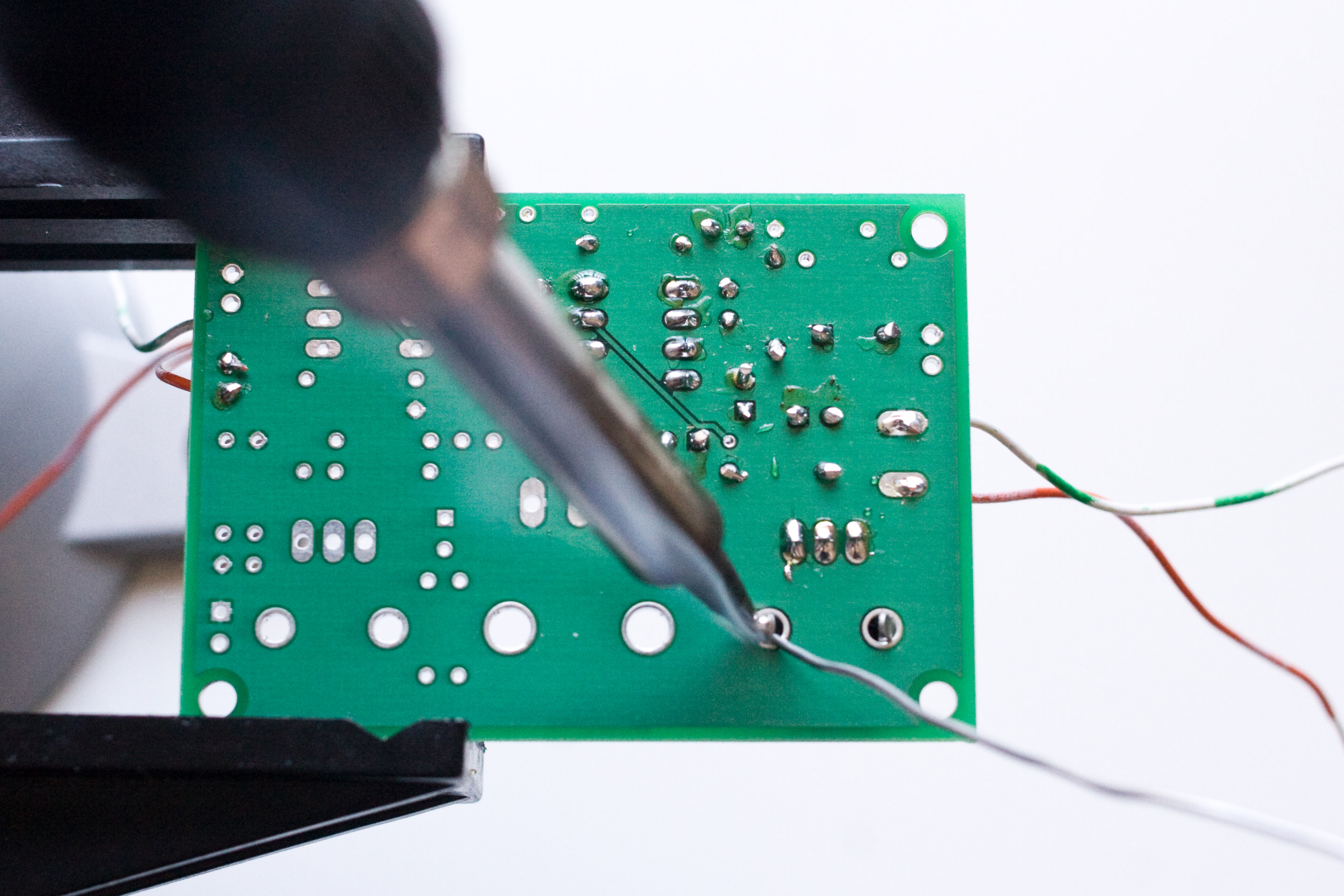
Solder and clip leads, if necessary. |
|
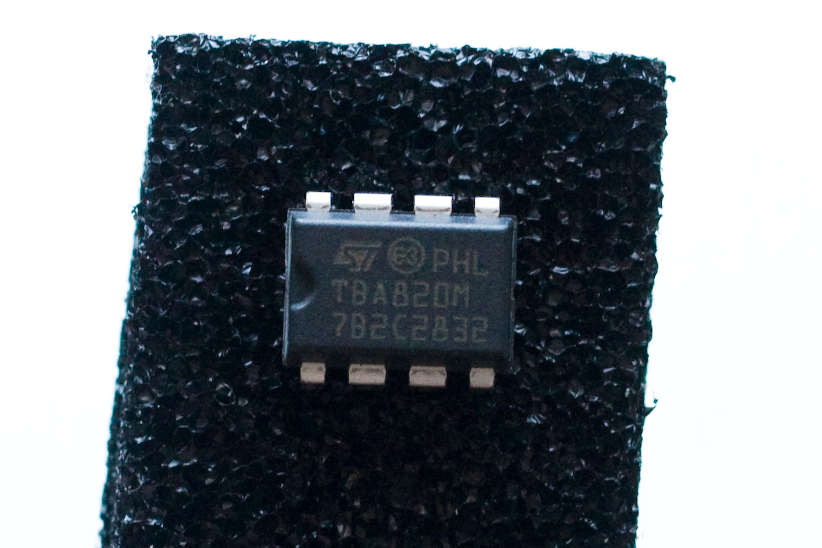
Now it is time for our amplifier chip. Make sure you grab the TBA820M, and insert it into the DIP socket. If you insert your opamp into the socket instead of the TBA820M then you will probably fry it. So make sure you have the right chip! |
|
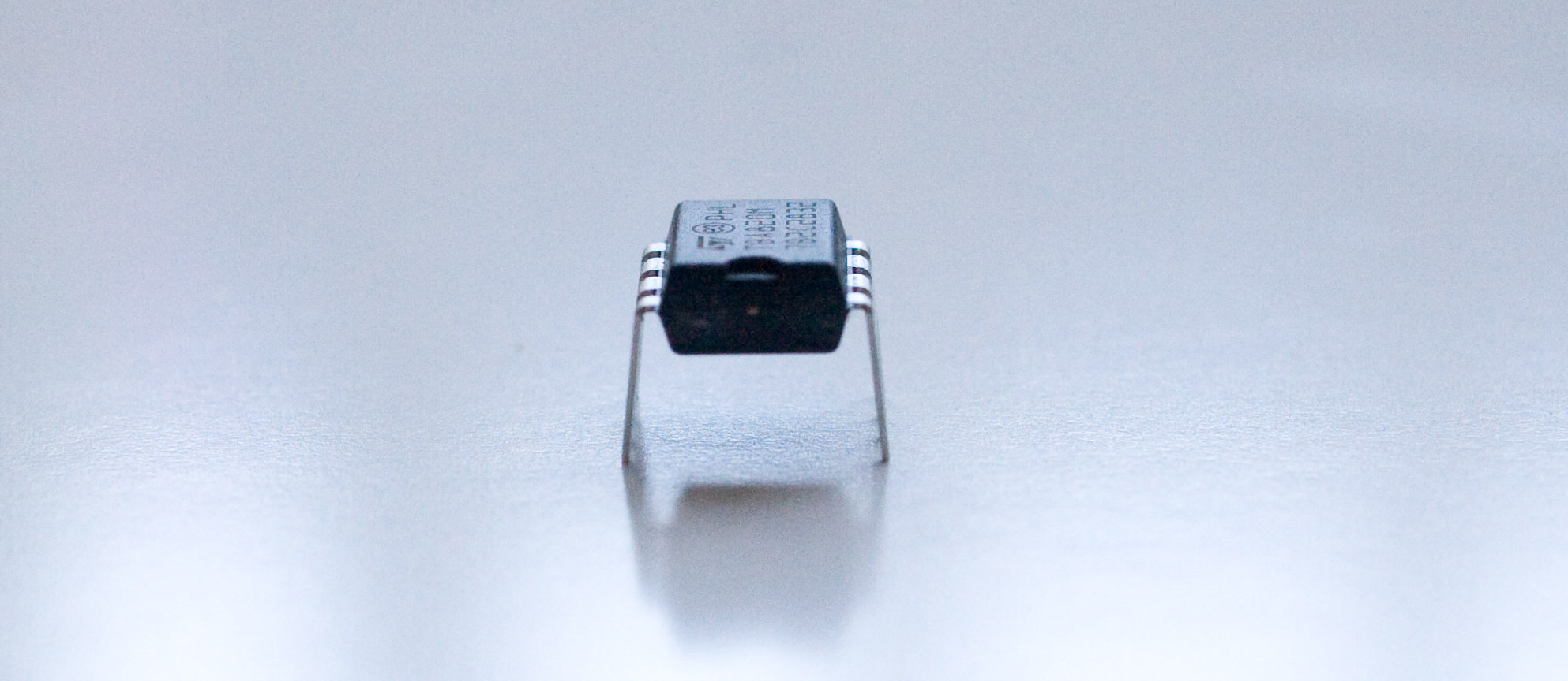
The chip comes from the factory with the leads bent outwards like this. We need to bend the leads in so they are more vertical, and will fit into the DIP socket better. |
|
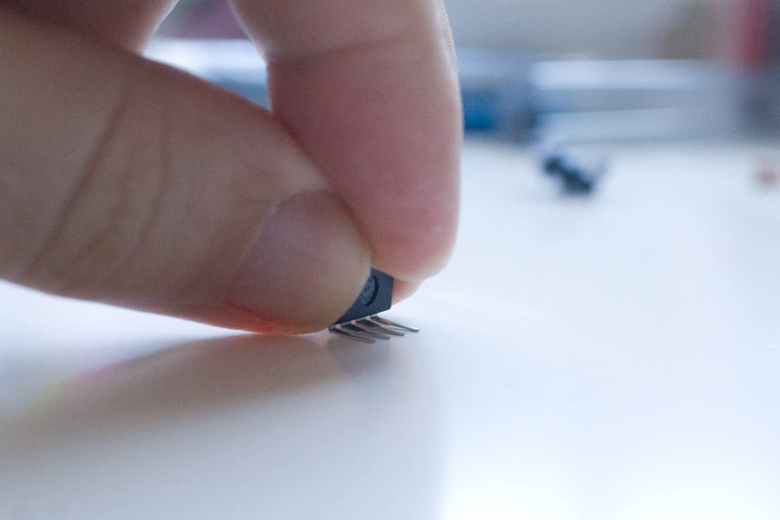
Lightly bend the leads against your workbench. Be careful not to bend them too much! |
|
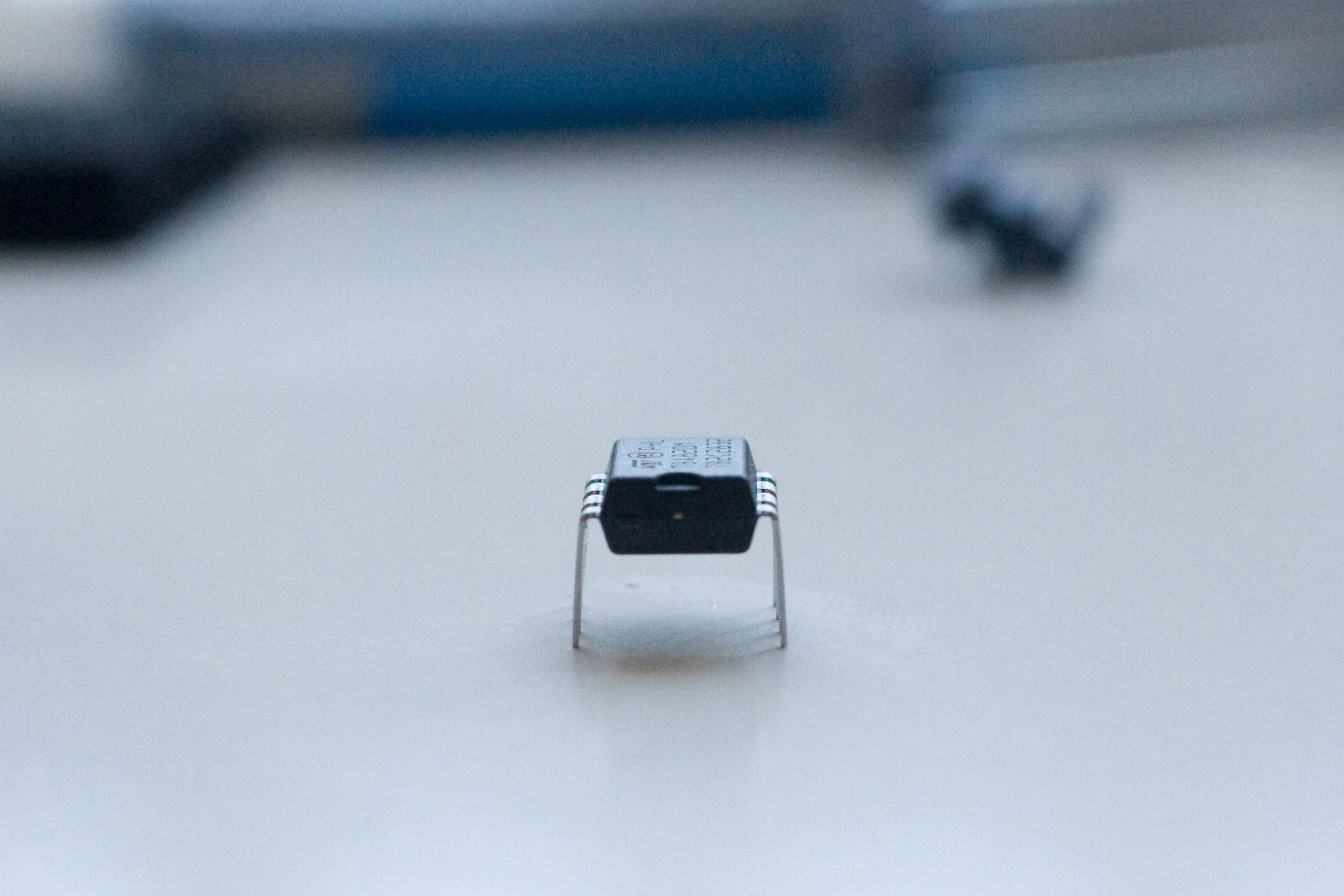
When you are done the leads should be vertical and not bent outwards. It looks subtle but it's really a big difference. |
|
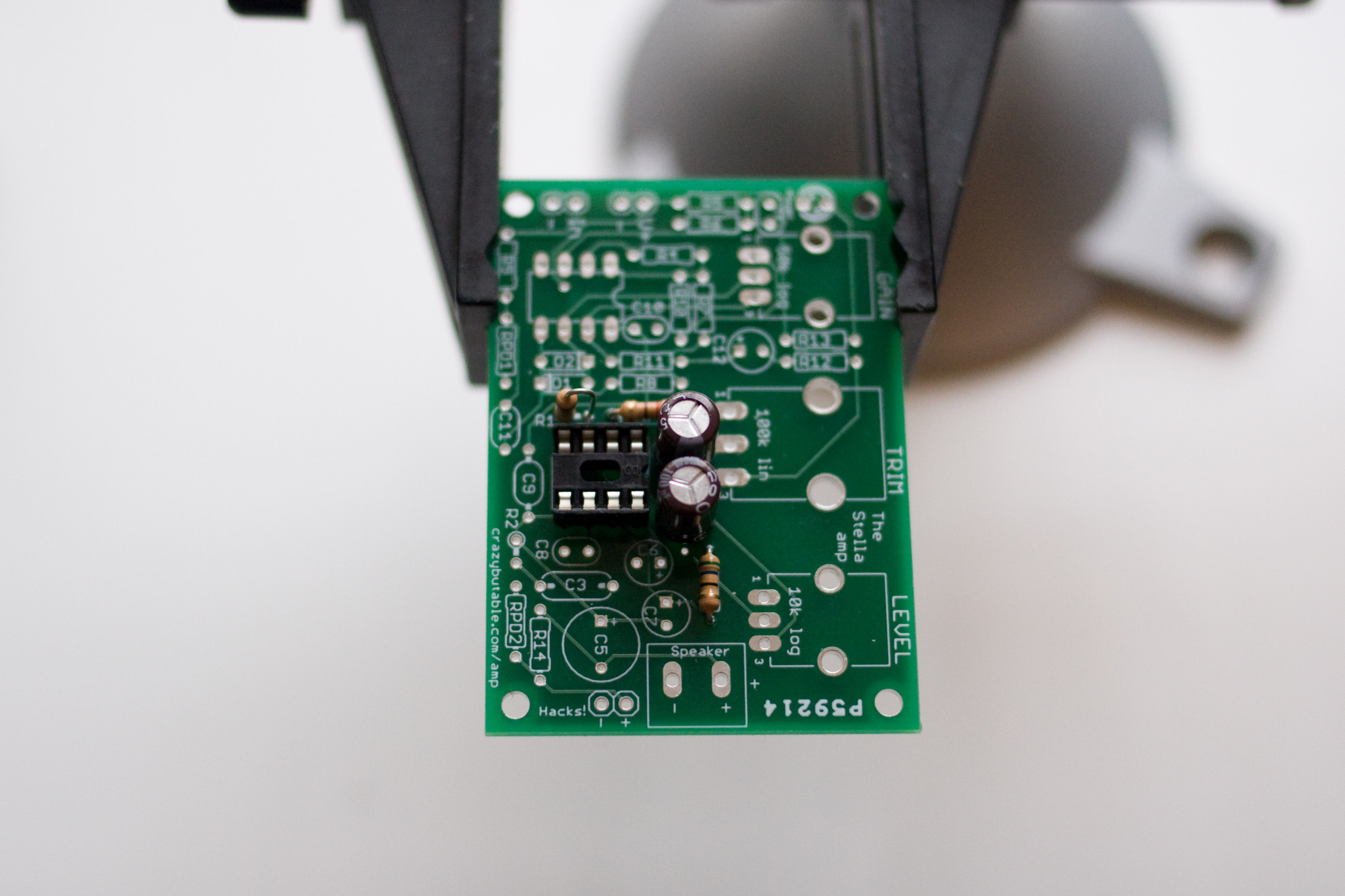
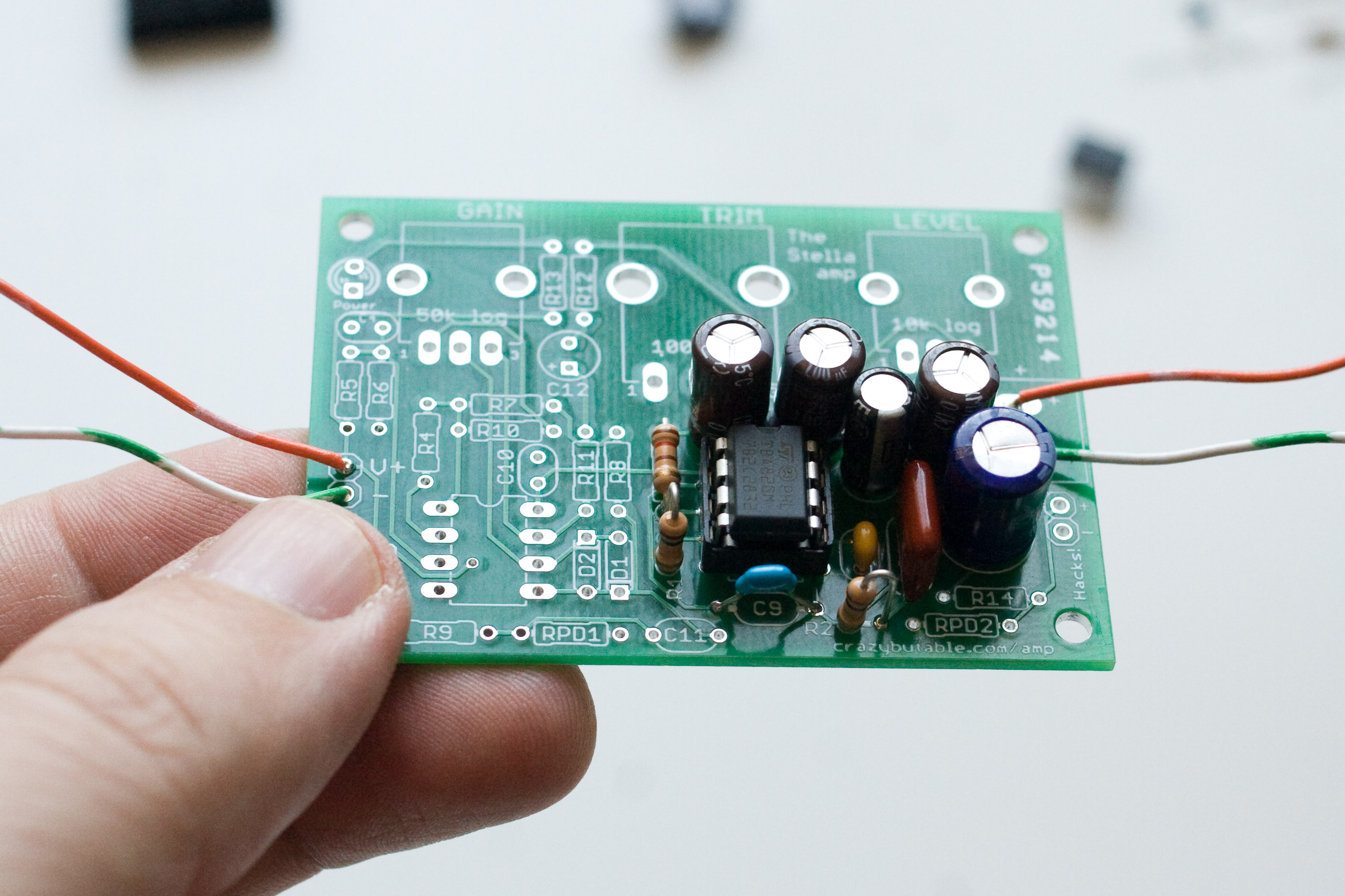
Snap the chip into place. The notch at the top of the chip should be pointing up towards the two 100uf capacitors. Don't insert this part backwards! Click this picture to see it full size if you are unsure. |
|
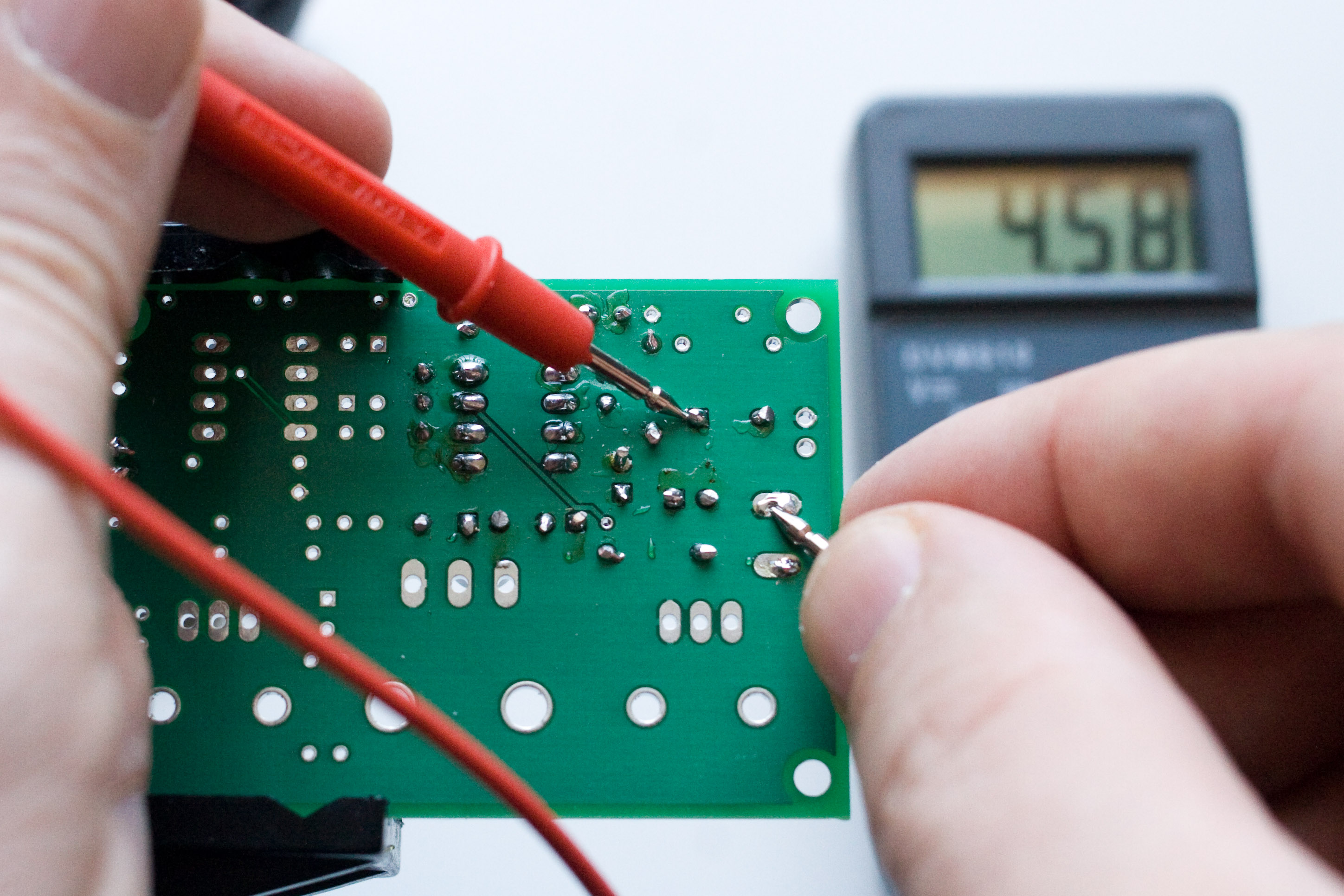
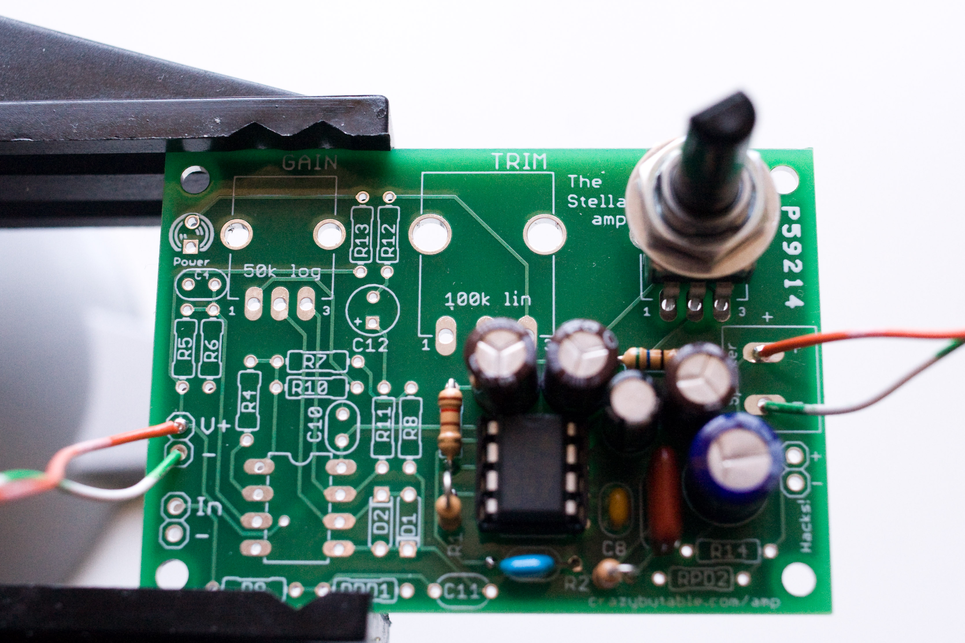
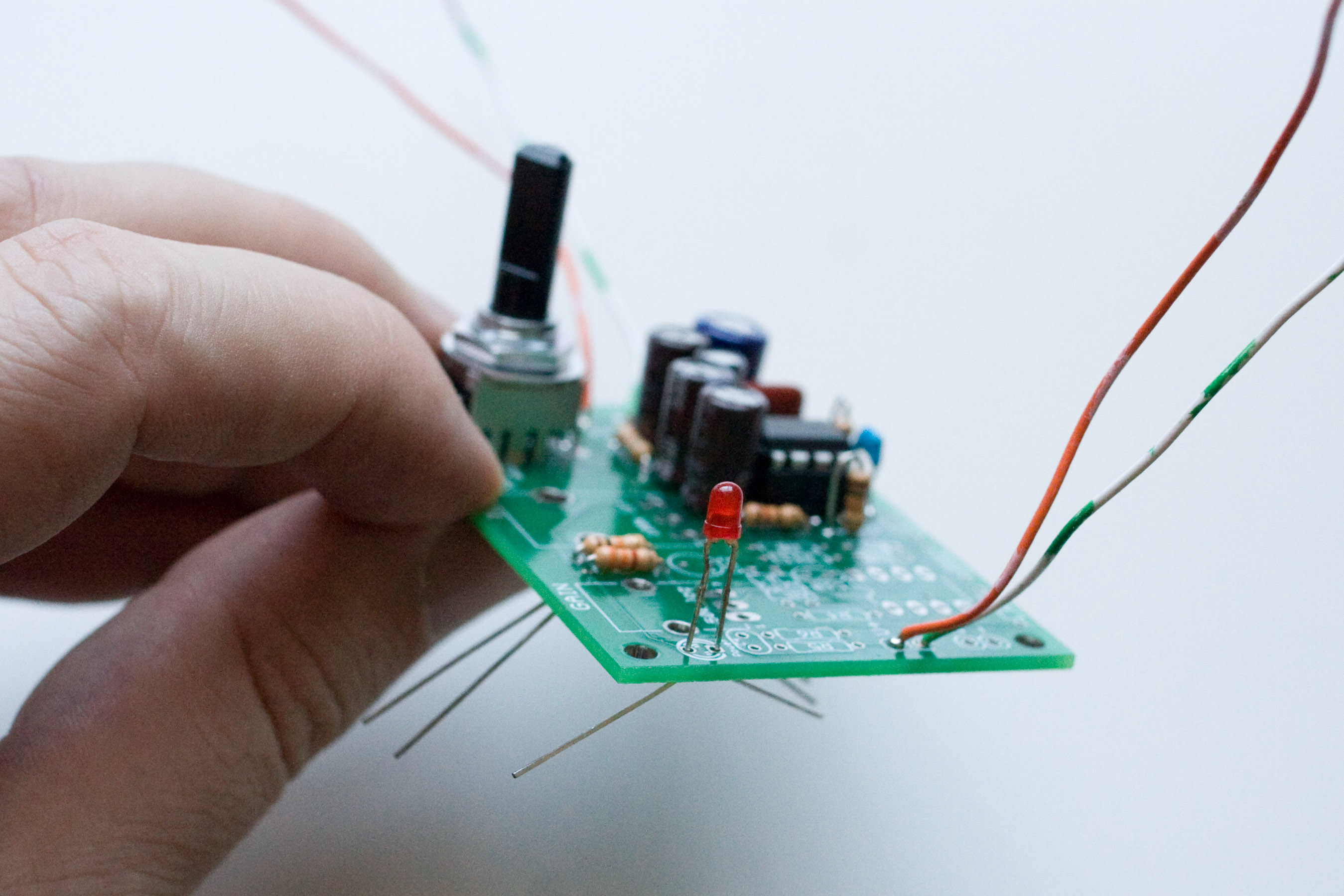
At this point we're ready to power it up and test it! Put your multimeter in a voltage measuring mode. Place the negative lead on a ground terminal (here I used the - speaker terminal). Put the positive lead on the + terminal of C. The voltage should read half the supply voltage, and, since I'm powering the board with a 9 volt battery, that's what I get. If you want to hear it amplify some audio, if you have an old walkman or CD player laying around you can inject that signal into the top of R1 (R1 is that first 10k resistor that you soldered in.) Hook up a speaker to the output terminals, and make sure that your speaker has a good enough power rating. Many small 2 or 3 inch speakers only have a .5 watt output power limit, and that is not enough, since our TBA820M can put out 2 watts! Then secure your input ground lead with an alligator clip to a convenient ground point, such as the - terminal of your power supply. |
|
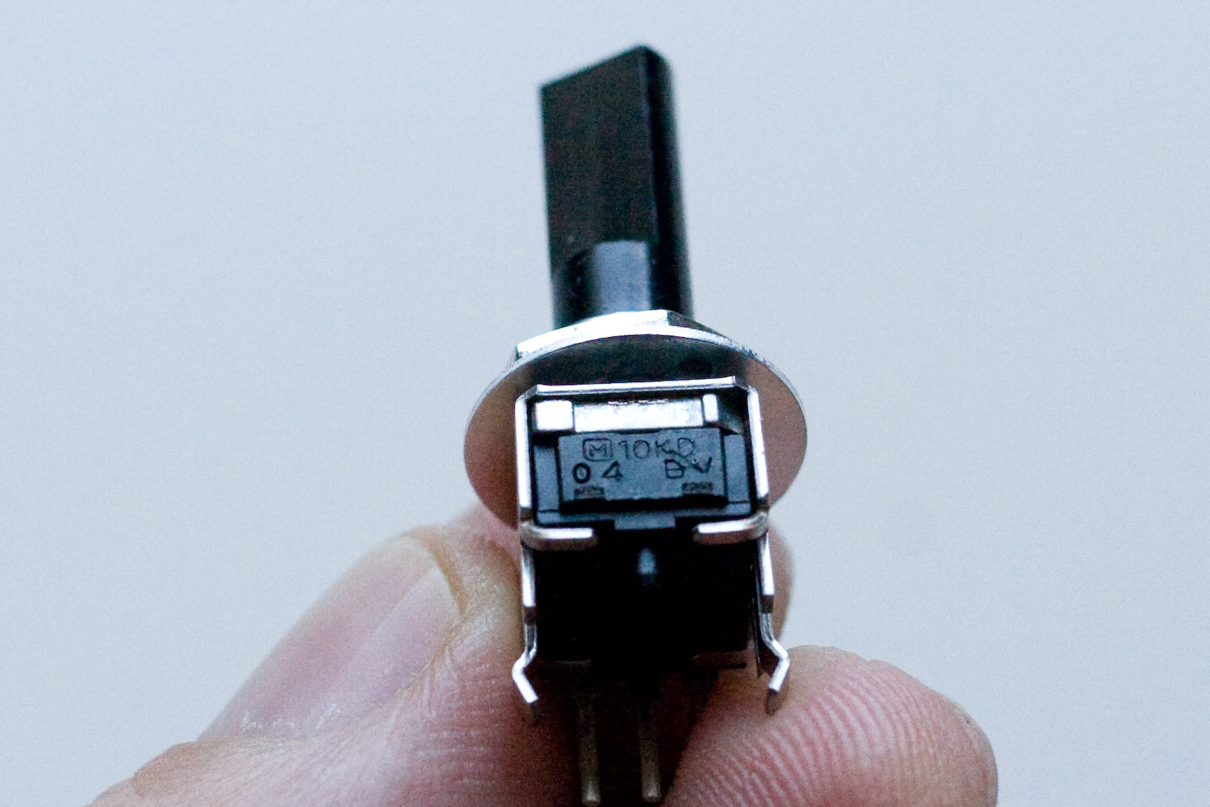
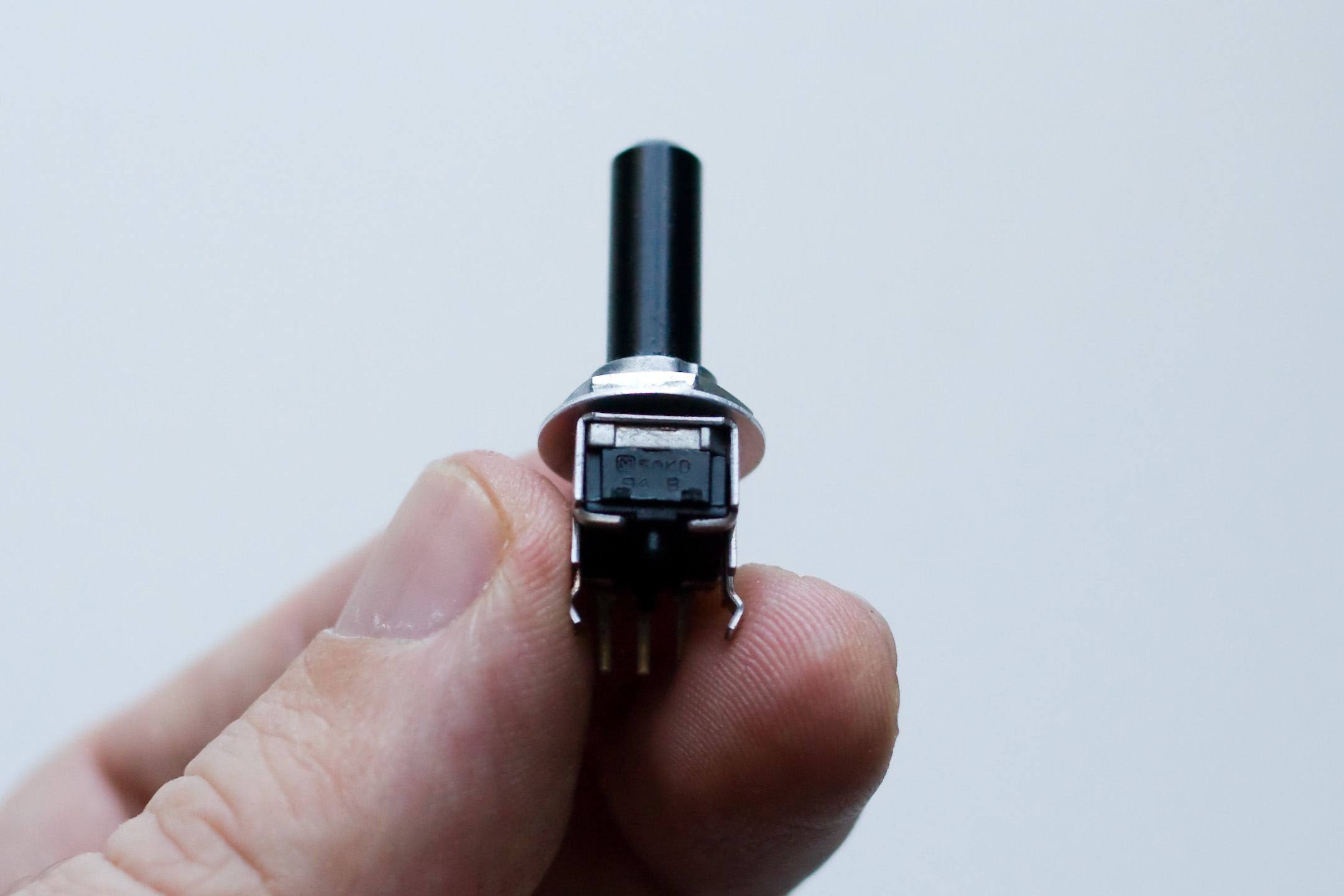
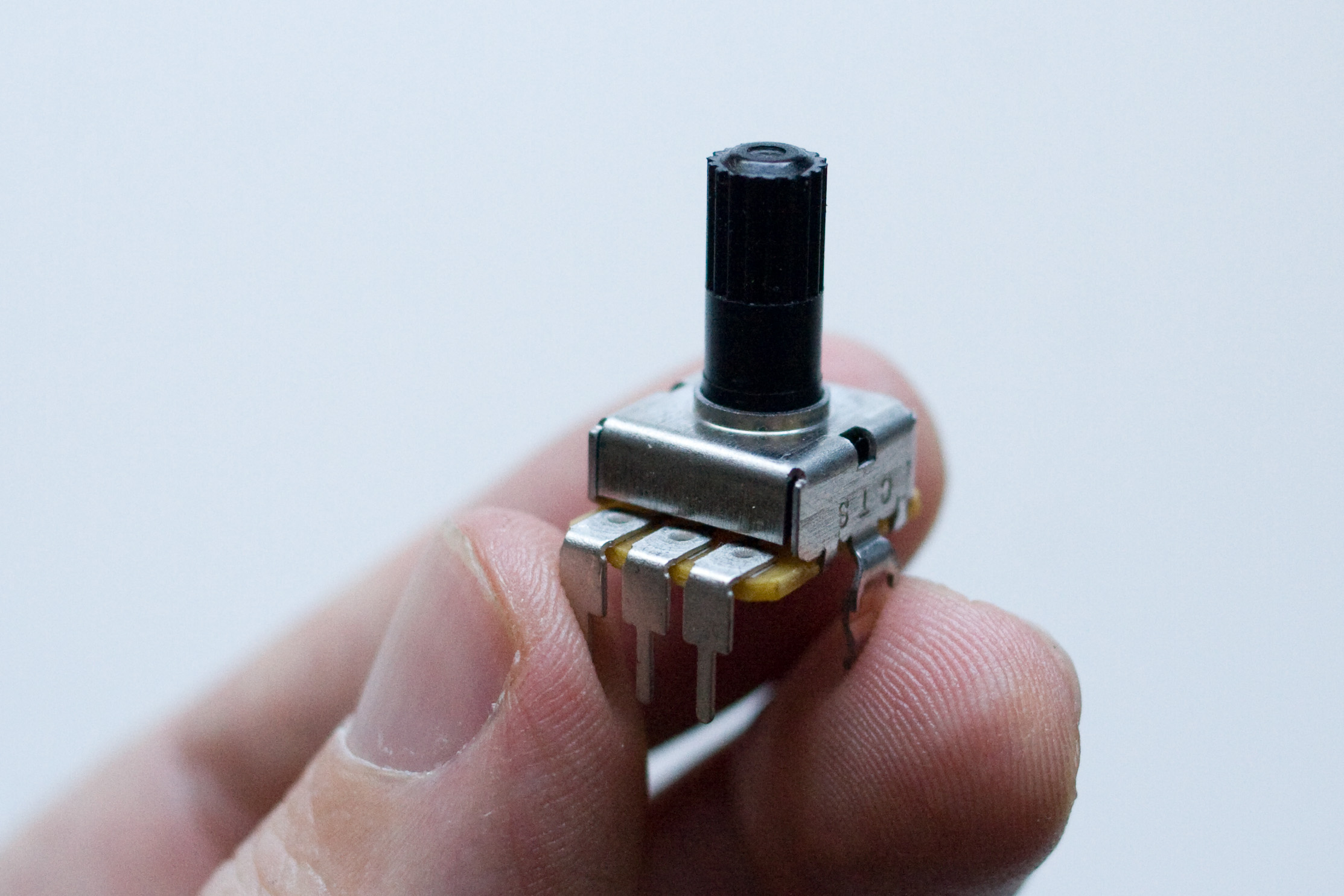
Time for one of the potentiometers! If you have a kit with external pots you can skip this step, since you'll be adding wires for all of your pots at the end. This is the level pot, and controls the final voltage level going into the amplifier. It is a 10k logarithmic pot; if you click on this picture to see the full size shot, you can see the 10k in tiny letters on the back. |
|
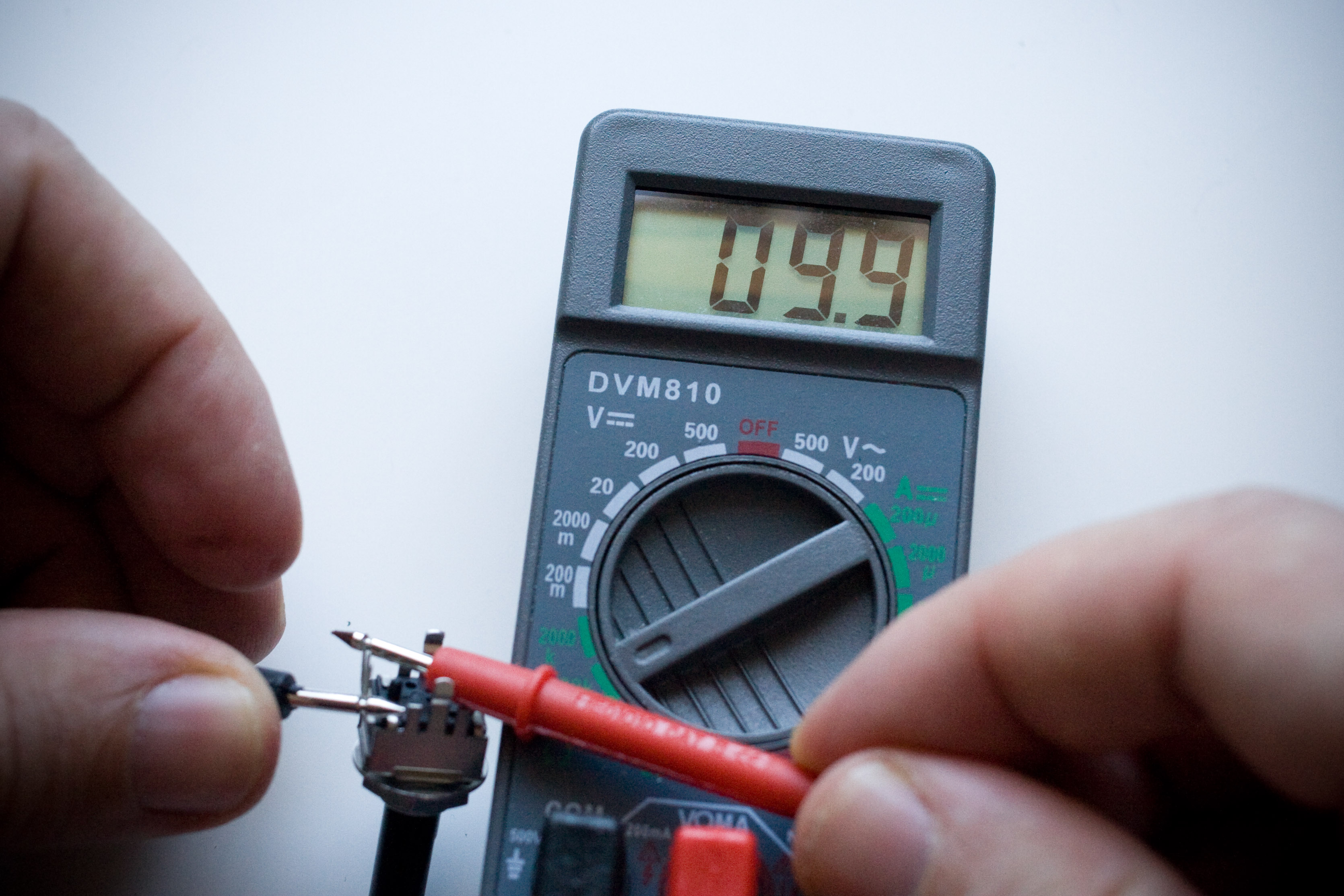
If your eyesight isn't that great, you can always get out the meter and measure it. Measuring the resistance between the two outer terminals, the meter says 9.9k ohms. If you accidentally swap the input stage and output stage pots then the output stage will have a different "feel" and the input stage won't have enough "oomph". |
|
It should click right in to place. |
|
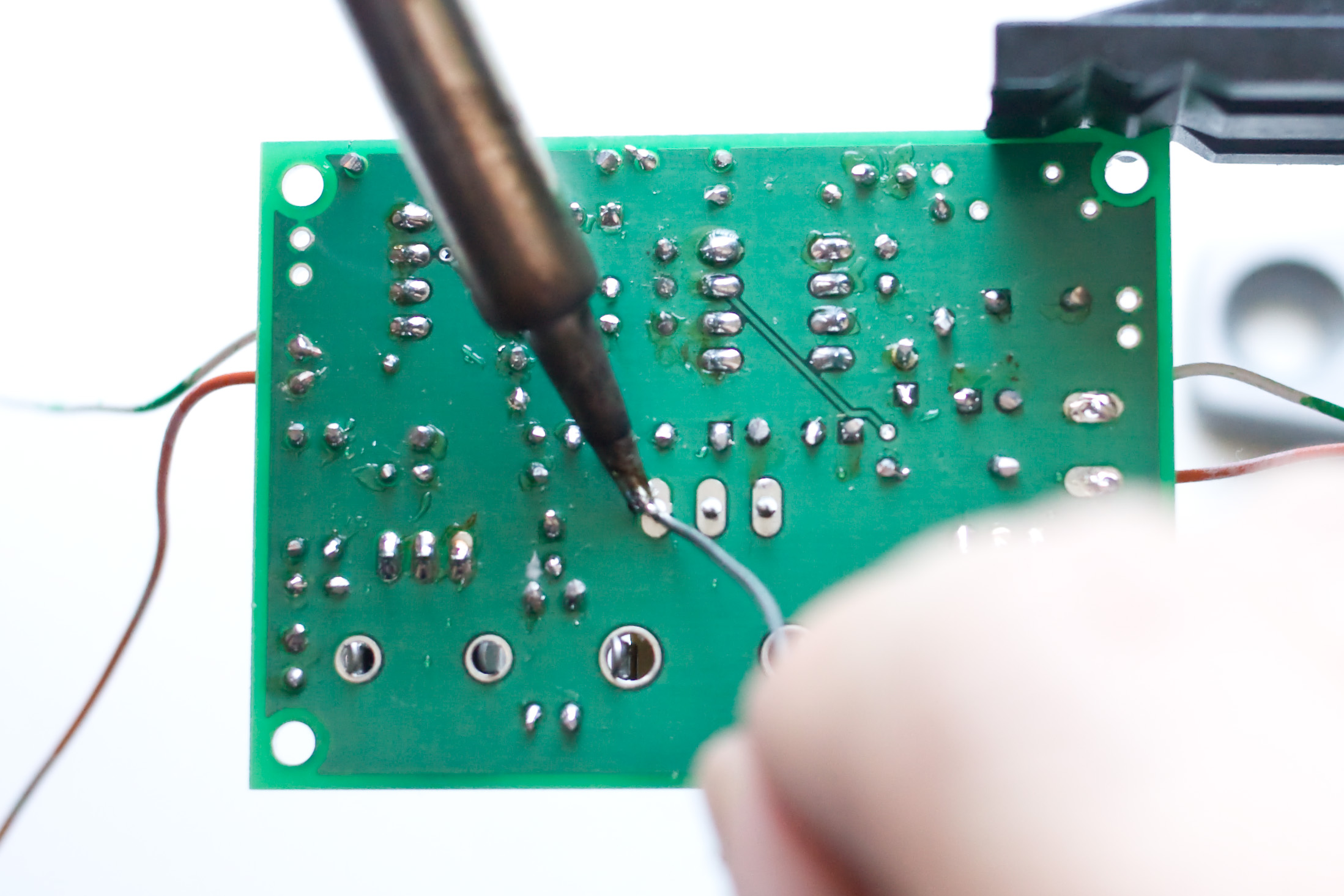
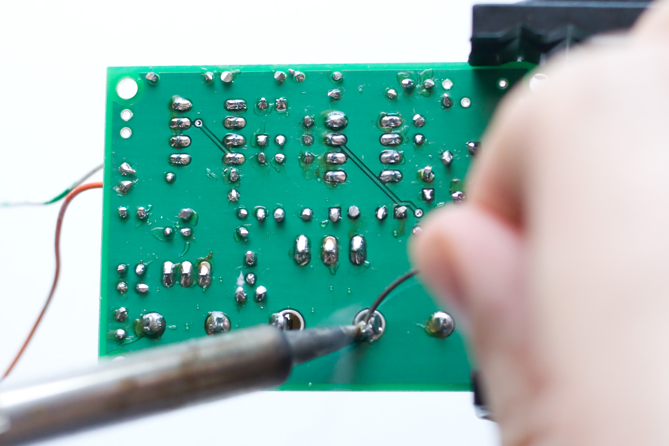
Solder it in. |
|
The bottom two holes are for strain relief and to keep the pot in place when you rotate it. Feed in enough solder to fill the hole, but don't keep feeding it in after that, or else you'll have a huge blob on the other side of the board. |
|
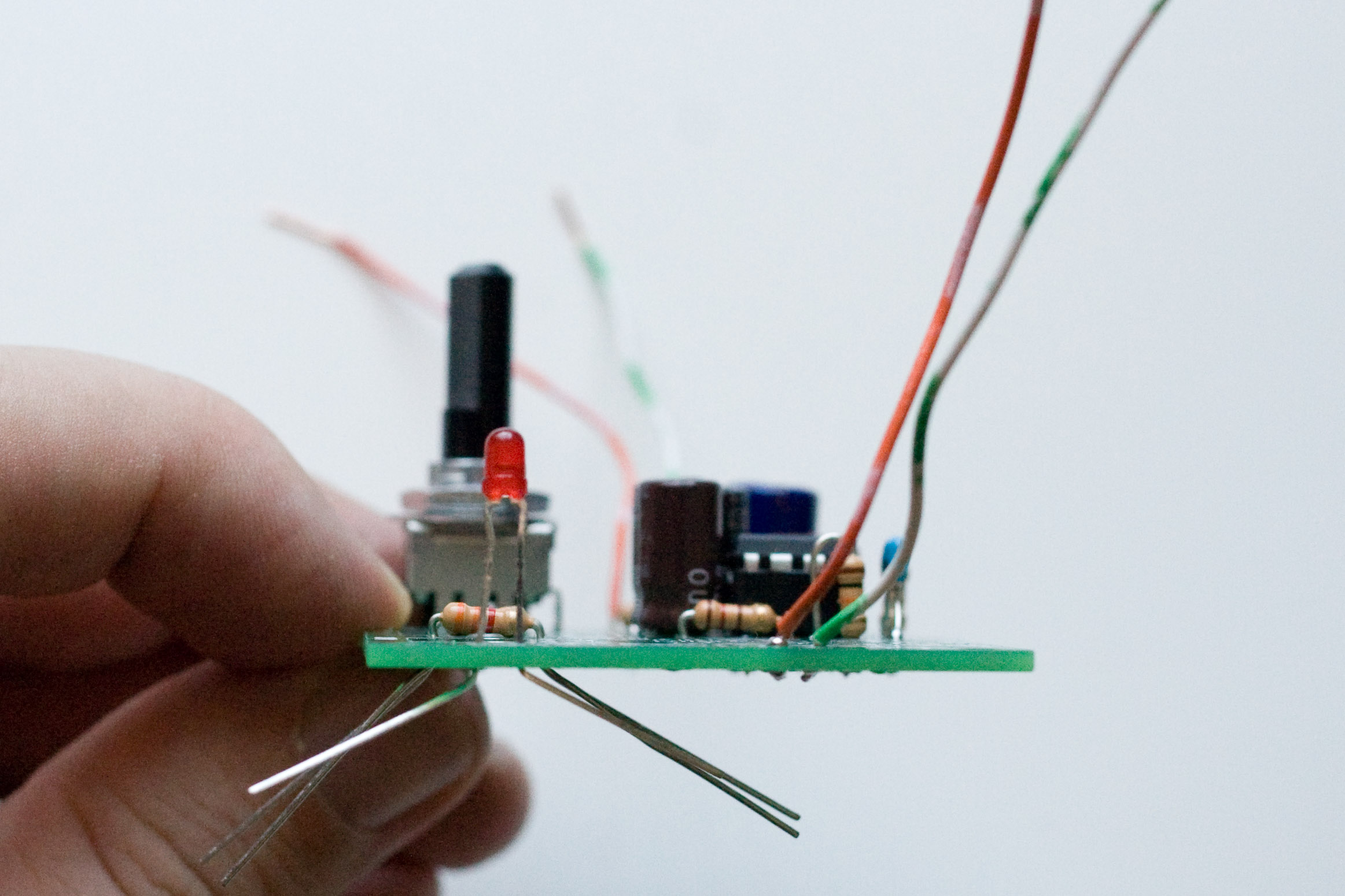
Next, we're going to place R12, R13, and the power LED. R12 is 10K, Brown, Black, Orange. Bend those leads like a staple and put it on the board. R13 is the current limiting resistor for the LED. The Stella amp kit comes with a high efficiency 3mm LED. Because the LED is so efficient, we can get away with a 3.3k current limiting resistor (even at 3 volts!), which will really help extend the battery life. If you decide to go with a different LED, you will probably need a different value resistor here. Or, if you find the stock LED is too dim in the daylight, you can replace R13 with a lower value resistor to get the brightness up. (You probably don't want to go with one that is less than 330 ohms, however.) Experiment with your power supply and a breadboard to figure out what you like. R13, as it is supplied with the kit, is 3.3k ohms. The color code is Orange, Orange, Red. The power LED has a + and a - side, just like elecrolytic capacitors. The + lead is a little longer and needs to go in the top hole on the board. (Later revisions of the board have a + symbol near the + hole.) |
|
LED height placement is a personal preference. If you have a kit with panel mount pots you will probably run wires to the board and mount the LED in the panel with the pots. Otherwise, if you are making a breadboard amplifier like this one, you can either mount the LED flush with PCB or you can mount it elevated off the board, like so. I prefer elevated but it really doesn't matter. |
|
Another view of the LED. |
|
Again, solder and clip the leads, you know the drill. |
|
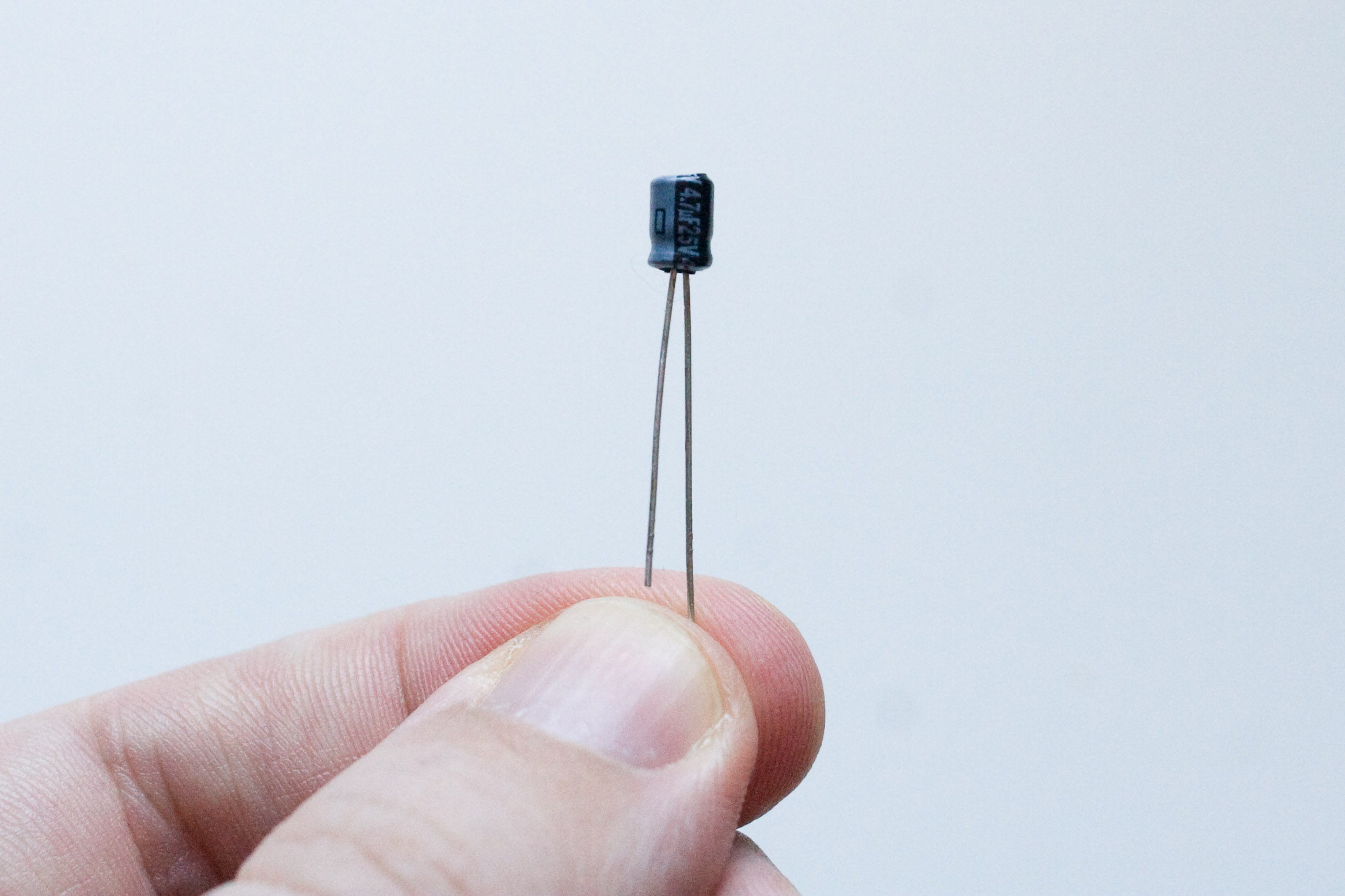
This cute little guy is a 4.7 uf electrolytic capacitor. His name is C12, and he blocks the DC component of the input stage's output from reaching the input of the output stage. Say that five times fast! |
|
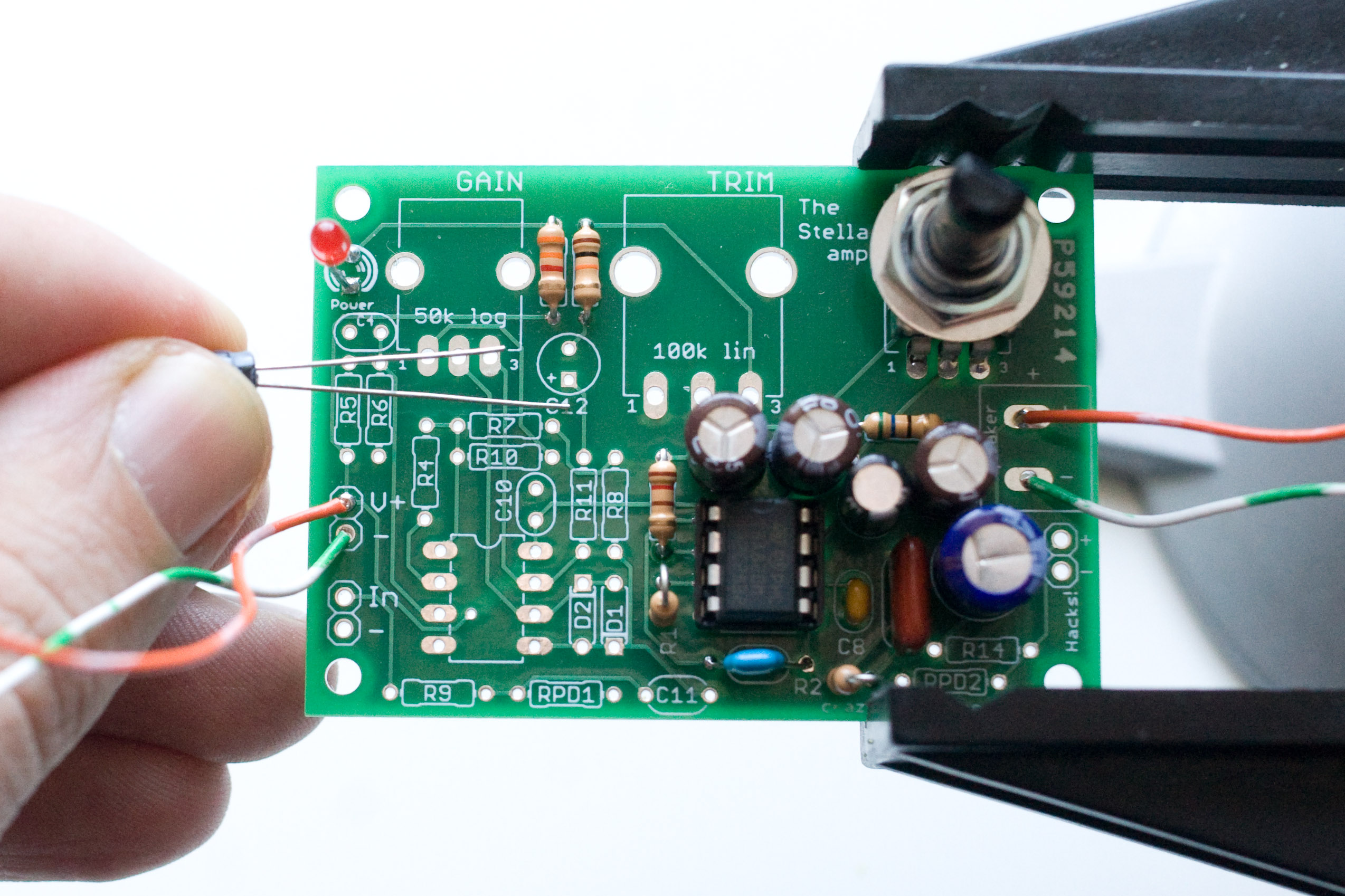
Don't let the tiny size fool you! I did say electrolytic, which you should know by now means it only goes in one way. The long lead is the positive lead and needs to go in the hole with the +. The "+" label means that side of the capacitor needs to remain at a higher voltage than the "-" side -- at all times! |
|
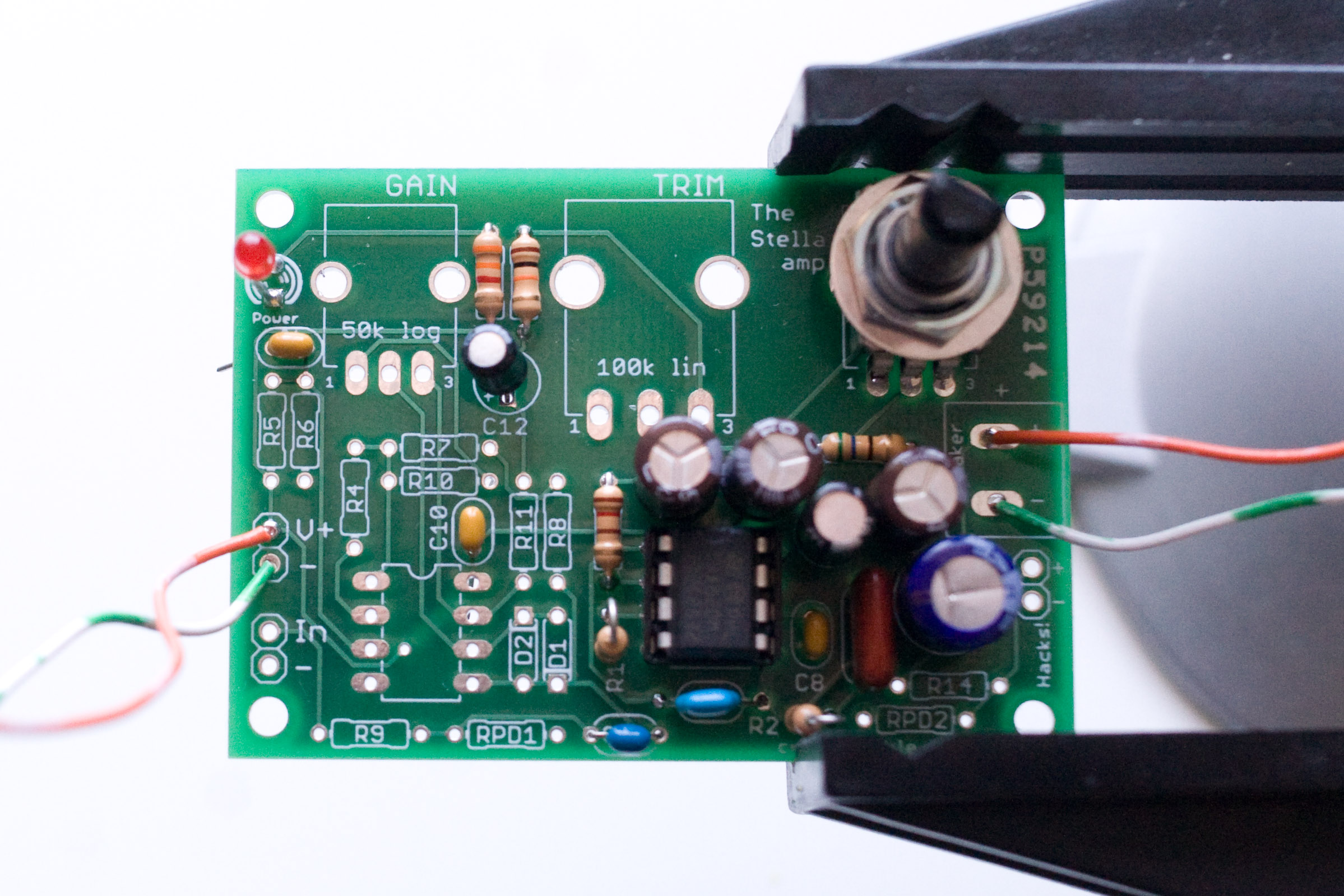
|
C11 is the input DC coupling capacitor. It is 1uf, and it is the dark blue capacitor on the right with short leads. It is a ceramic capacitor and is not directional. |
|
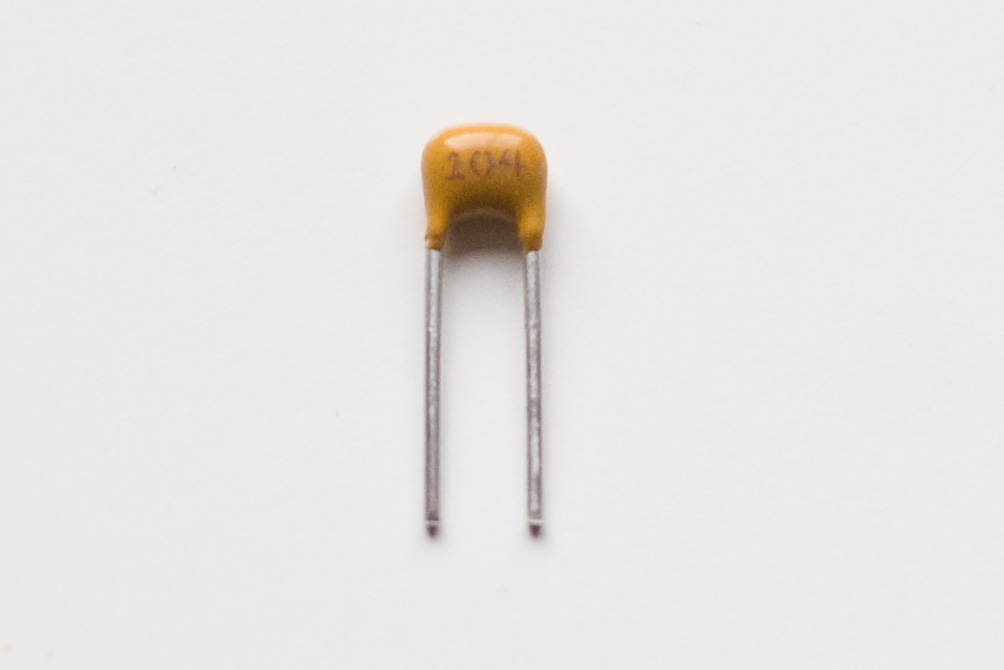
While we're here let's put in C4 and C10. They are both 0.1 uf ceramic capacitors. C10 is the decoupling capacitor for the op amp and C4 will help keep our virtual ground reference voltage divider stable. C10 and C4 are ceramic capacitors and can be placed on the board in either direction. They are little brown capacitors with short leads and "104" printed on them. |
|
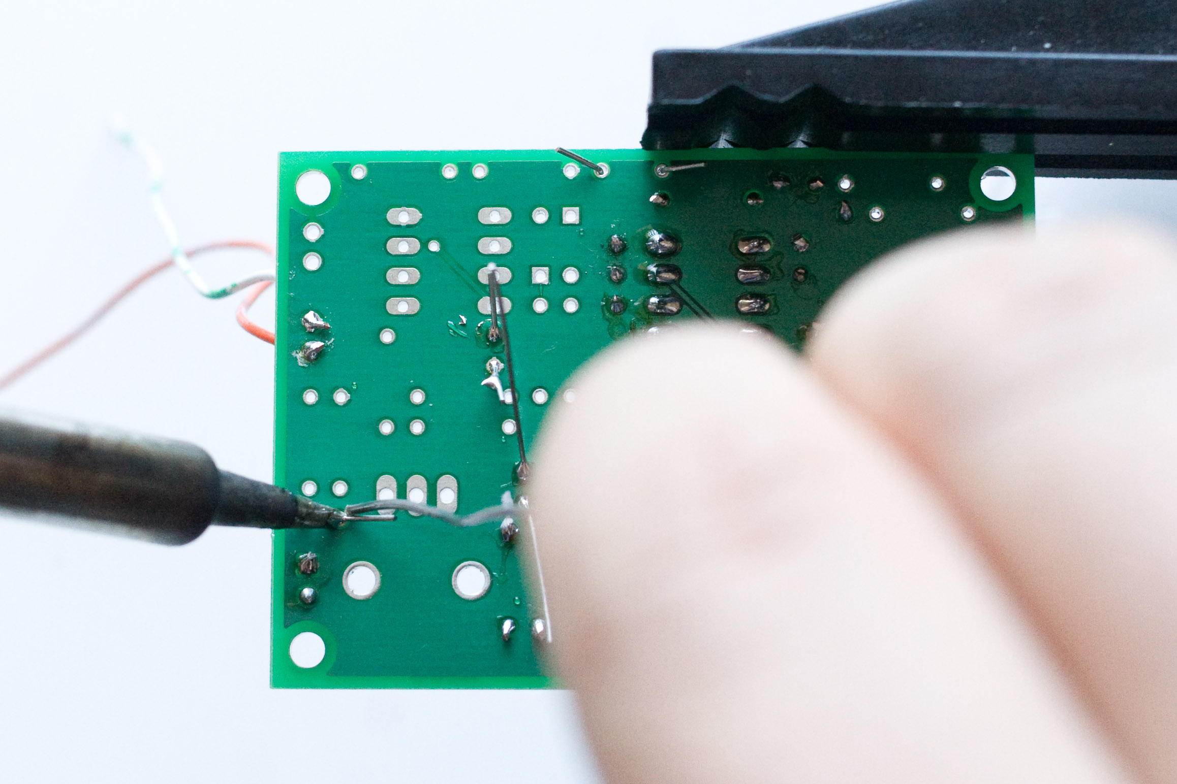
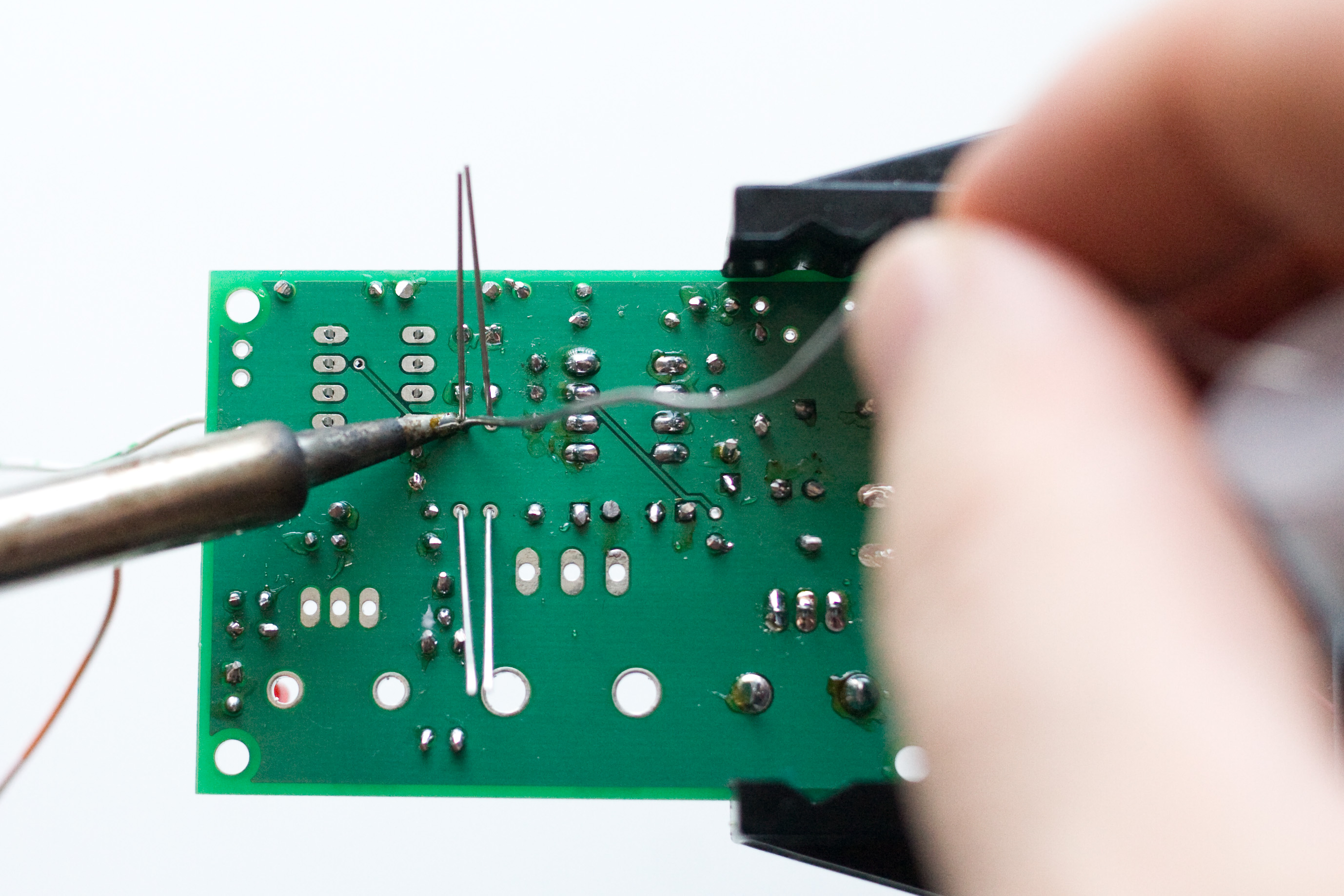
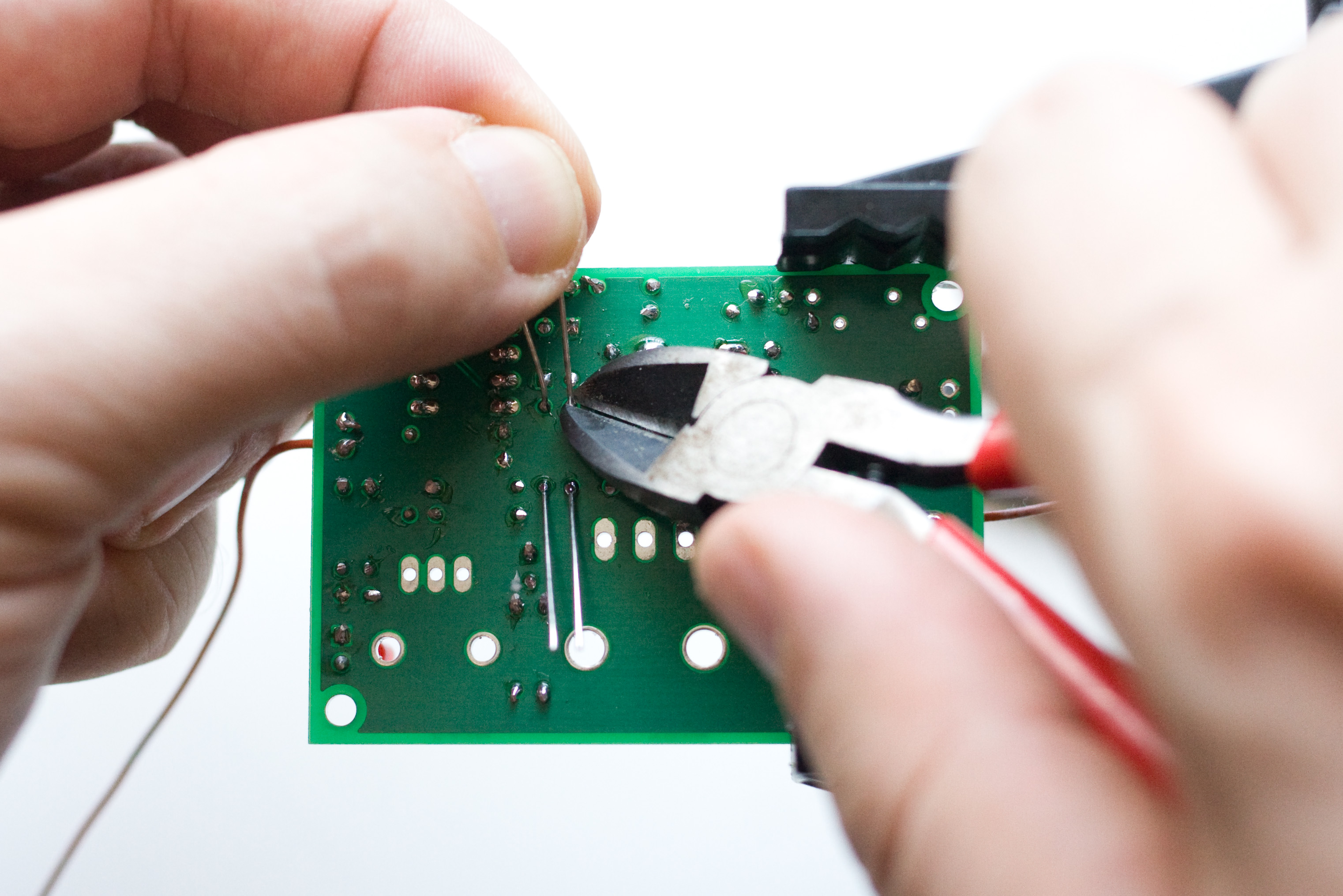
Solder! Solder and clip those leads. |
|
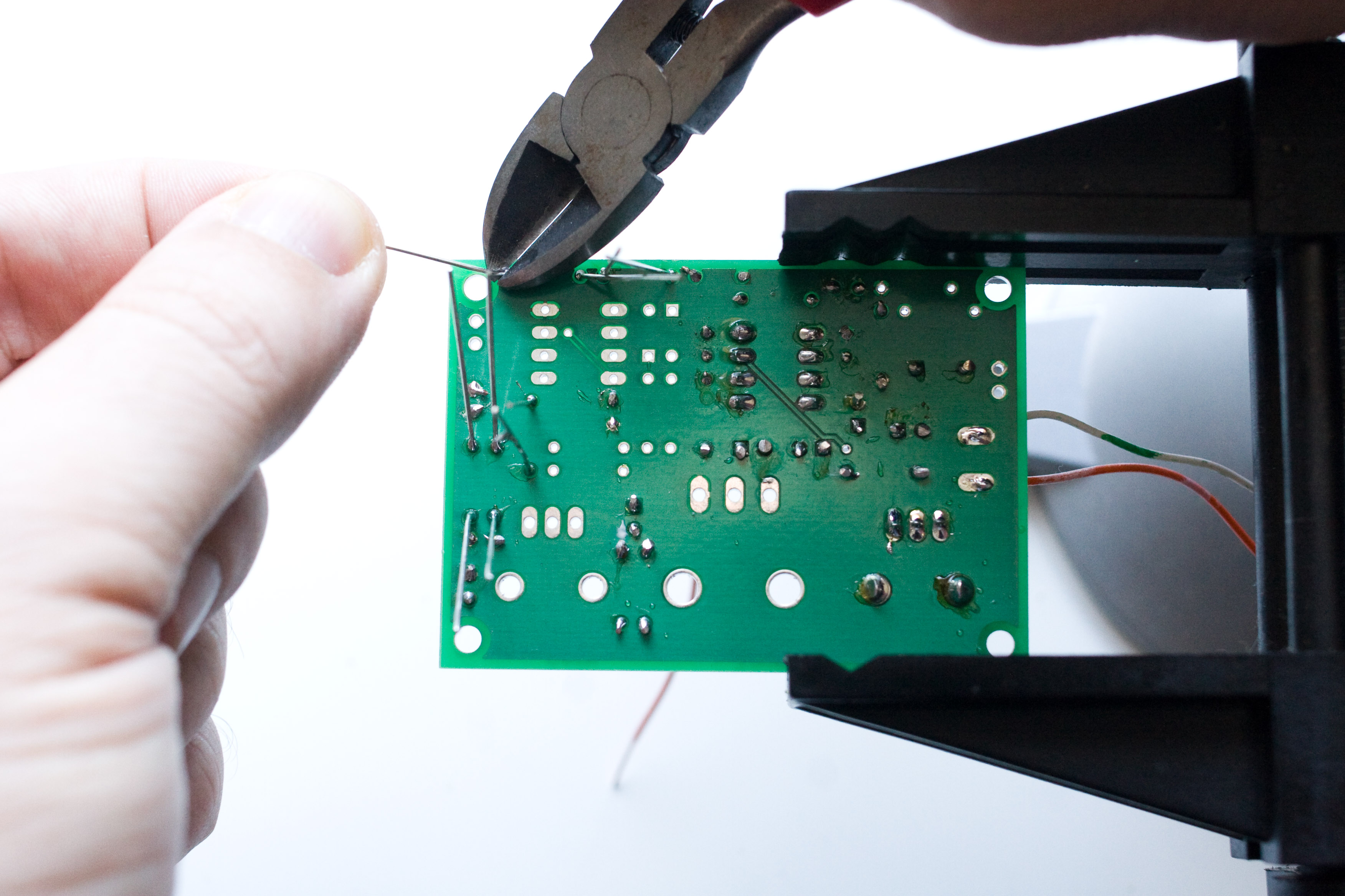
This isn't really a step, just an observation. While I was doing the soldering and lead clipping, my four year old was holding the camera remote, snapping the photos. It went something like this: I would start soldering, and say "Okay honey, press the button. Press the button! Take the picture! Take the pict- OW!" and then I burned myself on the soldering iron as I turned around to see Honey playing peekaboo with her little brother. Other times Honey (or her little brother, who was even more erratic) was entirely too enthusiastic, and would commence clicking and clicking and clicking, filling memory cards and draining batteries (and parental patience). This is one of those shots. Click to view it full size! |
|
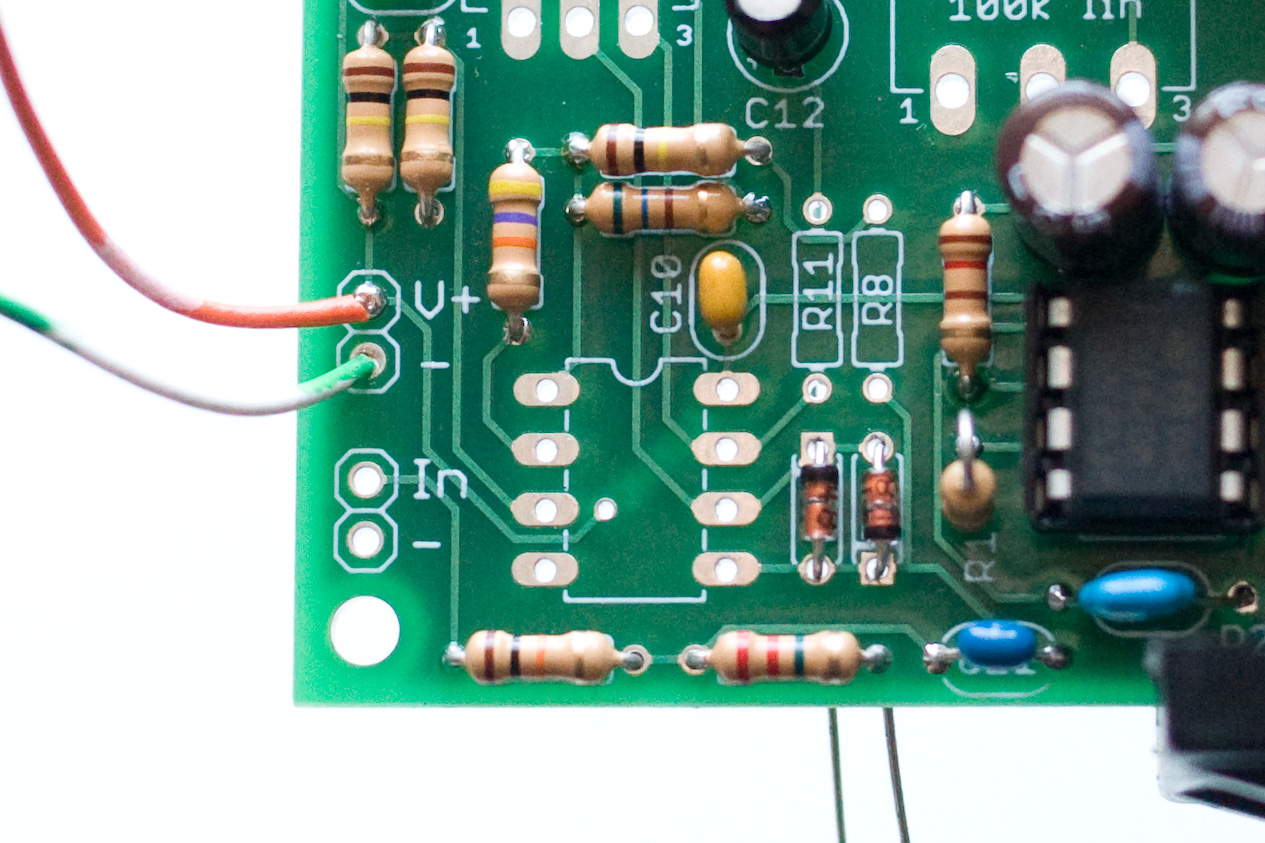
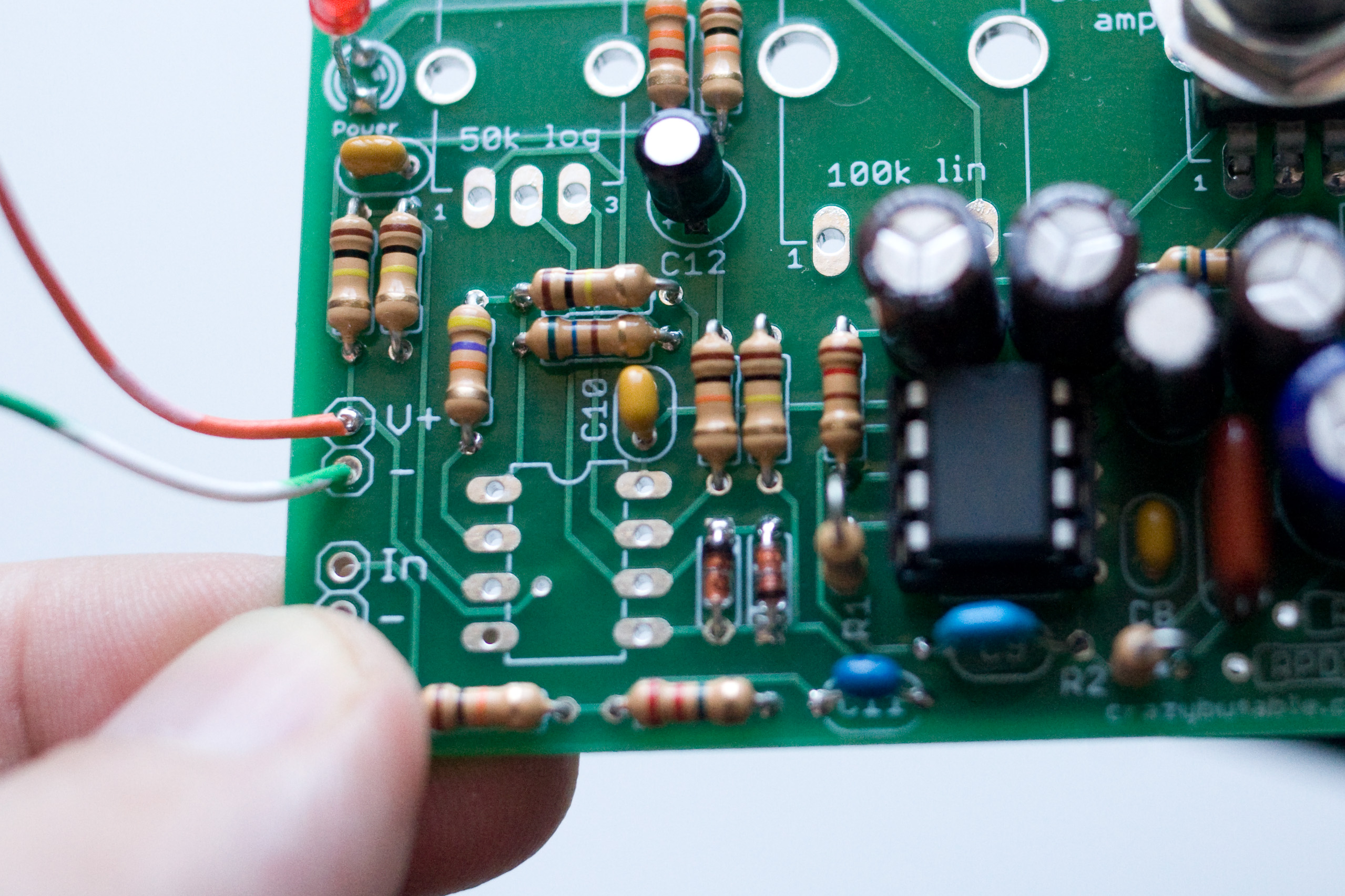
Now we're going to place five more resistors on the front end. R5 and R6 are 100k resistors (Brown Black Yellow), and they generate the bias voltage reference for our virtual ground. |
|
R4 is also part of our virtual ground circuit. R4 is 47k (Yellow Purple Orange). |
|
R9 and Rpd1 round off this set of resistors. R9 is an input protection resistor and is 10k (Brown Black Orange). Rpd1 is there to help prevent pops in the output if we wire up the amp as a guitar pedal, or hook a pedal up to our amp. Rpd1 is 2.2M (Red, Red, Green). |
|
Solder and clip the leads. |
|
R7 is the first half of the 200k input signal path to ground. It is 100 kiloohms (Brown Black Yellow). R10 sets the maxiumum gain of the input stage. It is a 560 ohm resistor (Green Blue Brown). You can figure out the maximum voltage gain by taking the value of the gain pot (50,000 ohms) and dividing it by this value (560 ohms) -- if you do that you'll see that the maximum gain is about 90. If you want a higher maximum gain because you are running the amp at 9-12 volts, then replace R10 with a 470 ohm resistor (gain of 106). A 330 ohm resistor would give a gain of 150, which is probably too much. If you set the gain on the input stage too high it will not make your amp louder, it will just sound like trash! [Side note here: if you have a 56 ohm resistor left and no 560 ohm resistor (Green Blue Black is 56 ohms, instead of Green Blue Brown, 560 ohms) then you put the wrong resistor in for R3 and you need to swap them.] |
|
Solder and clip the leads of R7 and R10. |
|
D1 and D2 are protection diodes for our opamp. Diodes only conduct current in one direction, so we have to put them in facing the right direction. Make sure the black stripe on the diode lines up with the white stripe on the silkscreen. You want one stripe to point up and one stripe to point down. You want them, in fact, to look like this picture here. |
|
Solder and clip the leads for the diodes. |
|
The last of the resistors: R8 and R11. R8 is 100k (Brown Black Yellow) and is the second half of the ground path for our input signal. R11 is 10k (Brown Black Orange) and is part of the output circuitry for our op amp circuit. Also, snap the last IC socket in for the op-amp. Remember to line up the notch on the socket with the notch on the silkscreen! They both should point up to the top of the board. |
|
Solder and clip the leads. The leads on the DIP socket are short enough that we don't need to clip them! If you have a kit with board mounted potentiometers, read on for instructions on installing the last two pots. If you have a kit with panel mount potentiometers and some wire, then skip the rest of this and go down to the "Panel mount potentiometers section." |
|
This is the gain pot. If you look very closely you can see the 50k on the back of the pot. |
|
Our Trim potentiometer is a 100k linear pot. Handsome, isn't he? |
|
Both the Gain and the Trim pots should snap in to place. Solder the connections. The leads are short enough that you probably don't have to clip them. |
|
These larger connections on the potentiometers are for mechanical strain relief, so don't be stingy with the solder! And now you're done with the main assembly! (If you have panel mount pots keep reading.) |
Panel mount potentiometer instructions
|
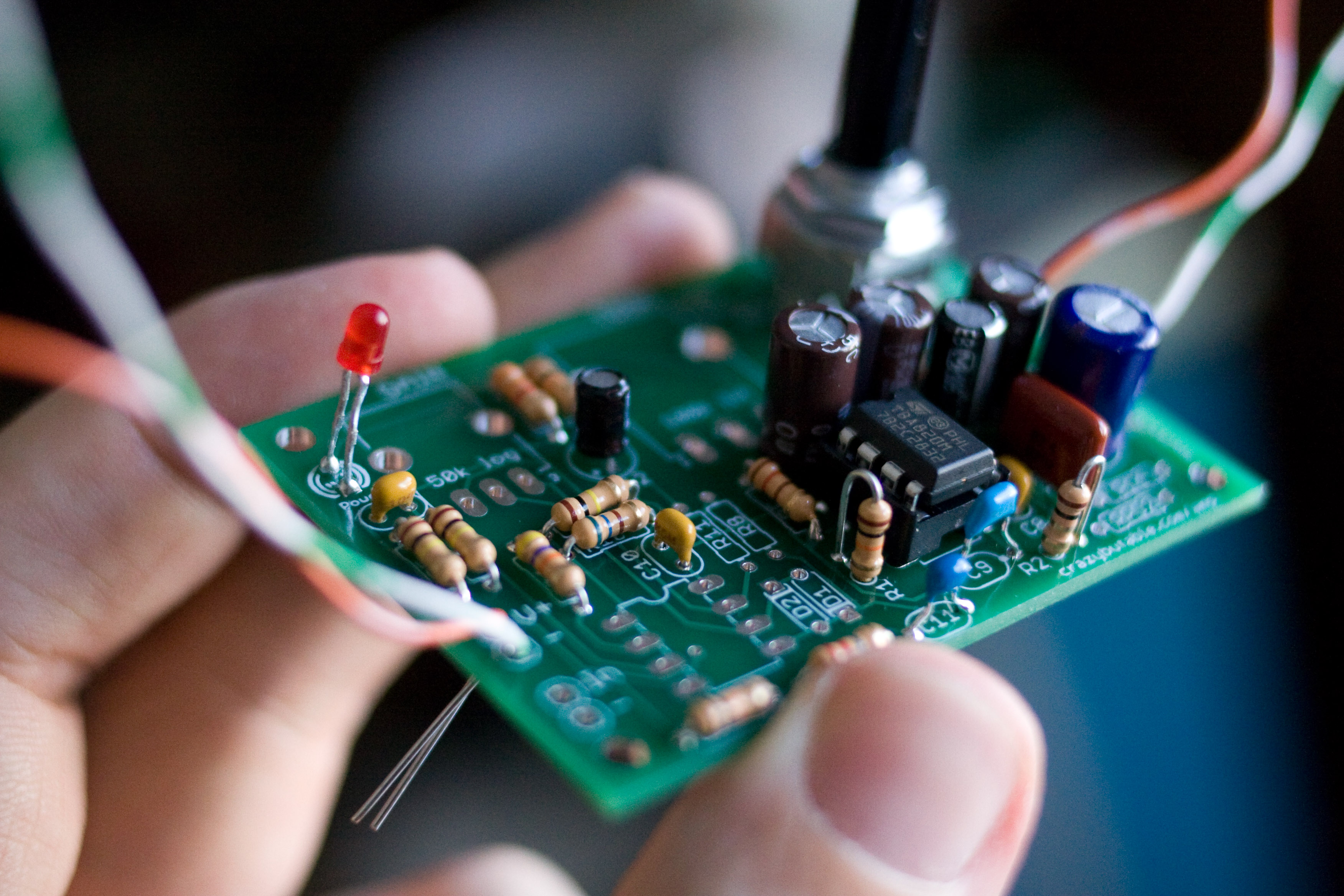
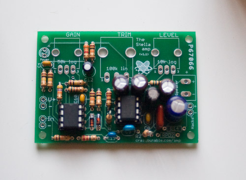
This is what your kit should look like when you're ready to install the pots and the external LED. |
|
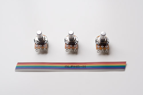
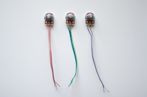
These are your panel mount potentiometers, and pretty rainbow wire! |
|
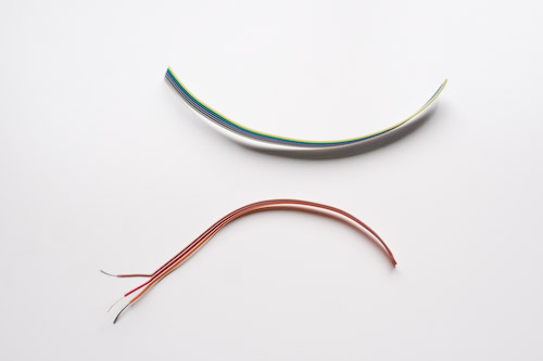
First we need to split the wire into three sections, with three wires in each section. When you're done you should have three wires: brown-red-orange, yellow-green-blue, and purple-grey-white. |
|
Strip about a 1/4 inch of insulation or so from the end of each wire. |
|
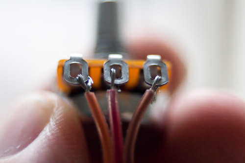
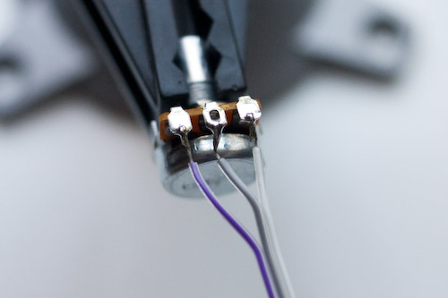
Start by soldering the wires to each of the pots. This is the 50k log taper pot. Holding the potentiometer like this, with the shaft pointing up, means that you are looking at the pins in order. Pin 1 is connected to the orange wire, pin 2 is connected to the red wire, and pin 3 is connected to brown. |
|
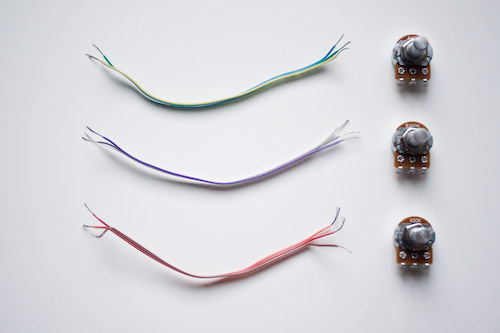
I've used the orange-red-brown wire for the 50k gain pot, the blue-green-yellow wire for the 100k trim pot, and the purple=grey-white wire for the 10k level pot. |
|
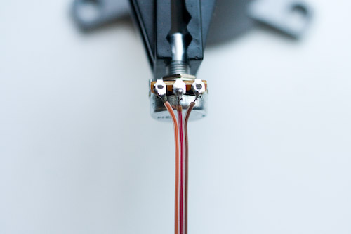
Secure each pot and solder all of the wires. Note that if you use a mini vise like this and press down with the soldering iron, the whole pot will rotate under you! Well, it surprised the heck out of me. Either be careful when doing it like this and use a light touch, or put the vise jaws on the body of the pot. Or use another method of securing your pots while soldering. |
|
As you can see, it does not matter if you fill in each of the solder lugs with solder or not, as long as each wire has a good connection. |
|
Finish up with the 10k level pot. |
|
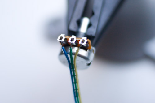
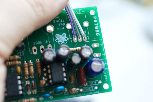
Now it's time to mount the pots on the board. Take a good look at the previous picture, and then this one. See how pin 1 is connected to the purple wire, pin 2 is connected to the grey wire, and pin 3 is connected to the white wire? Now look at this PCB picture. The purple wire goes by the 1 pin and the white wire goes by the 3 pin. |
|
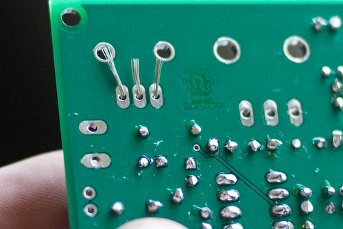
Flipping the board over gives you this view. (Sorry I don't have an action shot of soldering the wires but I broke my tripod and couldn't manage to hold camera, soldering iron, and solder all at once!) You may need to tape or otherwise support the wire while soldering because the stranded wire wants to slip out of the holes much more easily than the solid wire does. Solder those connections, and clip the excess stranded wire. Make sure to check between each pad to ensure you don't have a stray wire bridge between two pads. Solder the rest of the pots in. And you're done! Just hook up power wires, guitar signal wires, and speaker wires and you're ready to rock! |